Immersed combustor

A submerged burner and main combustion technology, applied in the direction of burner, gas fuel burner, combustion method, etc., can solve the problems of reducing the service life of the burner, energy waste, etc., to reduce resistance, reduce heat loss, structure compact effect

Active Publication Date: 2013-10-02
宁波中能连通机械有限公司
View PDF10 Cites 3 Cited by
  • Summary
  • Abstract
  • Description
  • Claims
  • Application Information

AI Technical Summary

Problems solved by technology

In the prior art, since this type of burner burns in a relatively closed area and mainly provides heat energy for the heat exchange bath water of the gasification device, the thermal efficiency utilization rate of the combustion energy and its own cooling are very important. If the thermal efficiency If the utilization rate is low, it will cause a waste of energy. If the burner itself cannot be cooled due to high temperature during combustion, the service life of the burner will be reduced.

Method used


Image

  • Immersed combustor
  • Immersed combustor
  • Immersed combustor

Examples


Embodiment Construction

[0023] Embodiments of the present invention will be described in further detail below in conjunction with the accompanying drawings.

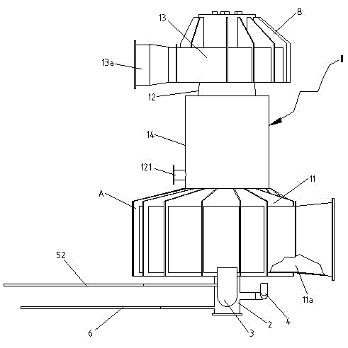
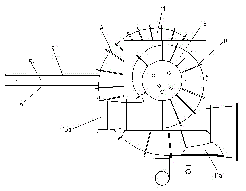
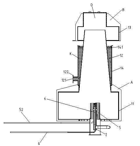
[0024] Figure 1 to Figure 7 Shown is a schematic diagram of the principle structure of the present invention.

[0025] The reference signs are: bottom volute reinforced rib A, top volute reinforced rib B, gas gathering chamber D, cooling water chamber K, furnace shell 1, bottom volute 11, smoke exhaust channel 11a, main combustion chamber Cone 12, cooling water inlet 121, connecting flange 122, top volute 13, main air inlet 13a, cooling water jacket 14, reinforcing plate 141, burner 2, air nozzle 21, fuel nozzle 22, fuel inflow Road 22a, spray hole 22b, cooling spray hole 22c, spray head 221, auxiliary intake pipe 3, fuel supply pipe 4, cooling circulating water coil 5, cooling water inlet pipe 51, cooling water outlet pipe 52, spray water pipe 6, spray head 61 .

[0026] Such as Figures 1 to 7 As shown, a submerged burner of the present ...


PUM


Abstract

The invention discloses an immersed combustor. The combustor comprises a furnace housing, wherein the furnace housing comprises a main combustion cone, a top volute and a cooling water jacket, wherein the main combustion cone is integrally communicated at the top surface of a bottom volute, the top volute is provided with a main tangential air inlet and is fixedly arranged at the upper end of the main combustion cone, and the cooling water jacket encircles the peripheral surface of the main combustion cone and is used for cooling the main combustion cone by circulating water; the bottom volute is internally provided with a combustion nozzle which is respectively connected with an auxiliary air inlet pipe and a fuel supply pipe, a circulation cooling water coiled pipe is sleeved on the periphery of the combustion nozzle, and an inner fuel passageway of the combustion nozzle is provided with an atomizing water pipe which jets water mist outwards to cool the combustion nozzle; a smoke removal channel is formed in the bottom volute in a tangent direction, the furnace housing is immersed and arranged in cooling bath water in such ways of feeding air at the upper part of the furnace housing and discharging smoke at the lower part of the furnace housing, the immersed depth of the furnace housing in the cooling bath water is more than the height of the furnace housing multiplied by one second, and the horizontal plane of the cooling bath water is lower than the edge of the upper opening of the cooling water jacket.

Description

technical field [0001] The invention relates to a combustion device, in particular to a burner using liquefied natural gas as fuel, in particular to a submerged burner. Background technique [0002] At present, liquefied natural gas (LNG) is becoming one of the fastest growing energy industries in the world with a high growth rate of about 12% per year. In recent years, my country's LNG projects have developed rapidly, and the demand for LNG has also increased rapidly. As an important equipment of the receiving station, the gasification device determines and affects the normal operation of the entire LNG receiving station and gas pipeline. The most widely used gasification devices in LNG receiving stations in the world are open-frame gasification devices and submerged combustion gasification devices. . The submerged burner is an important part of the submerged combustion gasification device. In the prior art, since this type of burner burns in a relatively closed area an...

Claims


Application Information

Patent Timeline
Patent Type & Authority Applications(China)
IPC IPC(8): F23D14/02F23D14/46
Inventor 蔡丽萍刘会明连海峰郭国义陈坤
Owner 宁波中能连通机械有限公司
Why Eureka
Try Eureka