Supercharge Your Innovation With Domain-Expert AI Agents!

Method for manufacturing a cement clinker, and cement clinker manufacturing facility

A technology of cement clinker and equipment, applied in the field of manufacturing cement clinker, can solve problems such as multi-NOx gas

Active Publication Date: 2011-05-11
菲弗斯有限公司
View PDF4 Cites 7 Cited by
  • Summary
  • Abstract
  • Description
  • Claims
  • Application Information

AI Technical Summary

Problems solved by technology

The use of such a combustion chamber additionally requires the removal of ash from it and also has the disadvantage of producing more NOx gases

Method used


Image

  • Method for manufacturing a cement clinker, and cement clinker manufacturing facility
  • Method for manufacturing a cement clinker, and cement clinker manufacturing facility
  • Method for manufacturing a cement clinker, and cement clinker manufacturing facility

Examples


example 1

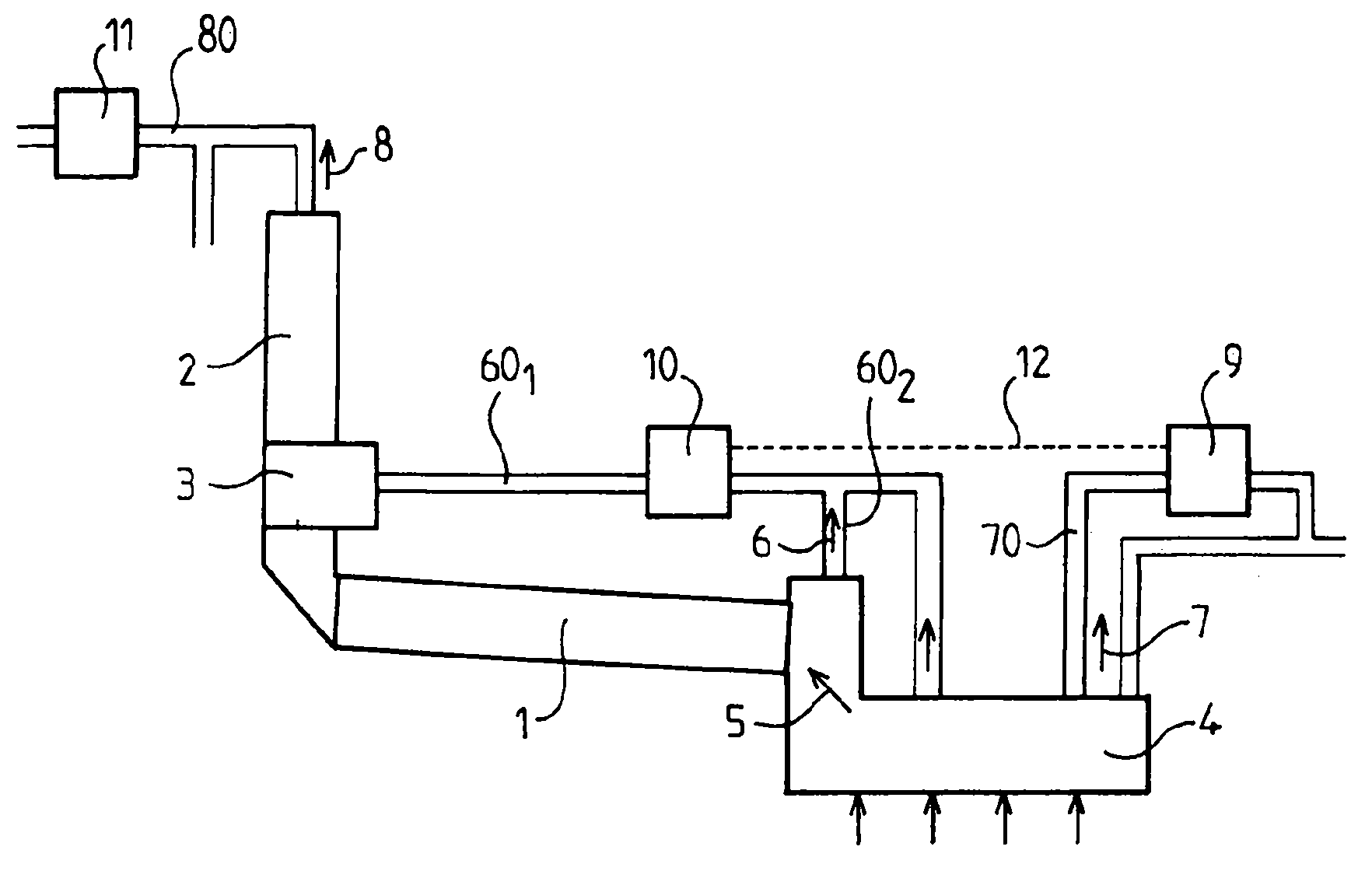
[0072] Example 1 (Prior Art):

[0073] The considered plant, as known in the prior art, is a clinker production unit of medium scale, or representing the capacity of a large number of existing units, producing 5000 tons of clinker per day. This plant consumes 3000 kJ supplied in the form of fuel per kg of clinker produced, of which 62.8% is introduced at the precalciner. Thus, the power generated from the fuel in the precalciner was 108.8 MW.

[0074] Clinker cooler especially produces: 117000Nm 3 / h, tertiary air at 890°C, which is supplied to the combustion of the pre-calcination reactor; 210000Nm 3 / h, exhaust air at 245°C. The flow rate of the smoke in the cyclone preheater is 286200Nm 3 / h at a temperature of 320°C.

[0075] An exchanger located on the exhaust air route of the cooler reduces the temperature of the gas from 245°C to 135°C and exchanges 8.6 megawatts of power. Considering the possible low temperature of the fluid of the exchanger, as long as a fluid...

example 2

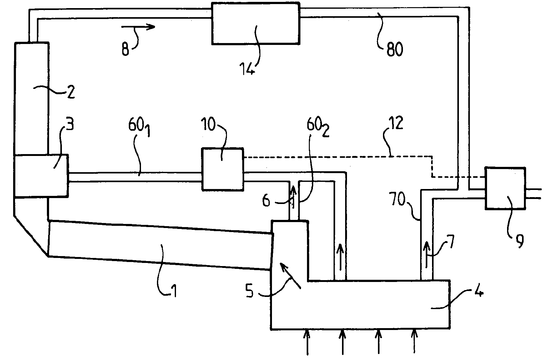
[0079] Consider the plant according to example 1 of the invention, in which an exchanger is placed in the route of the tertiary air and reduces the temperature of the tertiary air to 700°C. The amount of fuel introduced into the pre-calcination reactor must be increased, and the new operating conditions of the plant are described below.

[0080] The power generated from the fuel in the precalciner was 117.8 MW. Clinker Cooler now produces 127900Nm 3 / h, 860°C tertiary air, and 199200Nm 3 / h, exhaust air (excess air) at 235°C. The flow rate of the smoke in the cyclone preheater is 300000Nm 3 / h at a temperature of 335°C.

[0081] The exchanger (second exchanger) located on the route of the tertiary air, which reduces the temperature of the tertiary air from 860°C to 700°C, exchanges 8.3 MW of power. An exchanger (first exchanger) located on the route of the exhaust air (excess air) of the cooler reduces the temperature of the gas from 235°C to 135°C and exchanges 7.4 MW of...

example 3

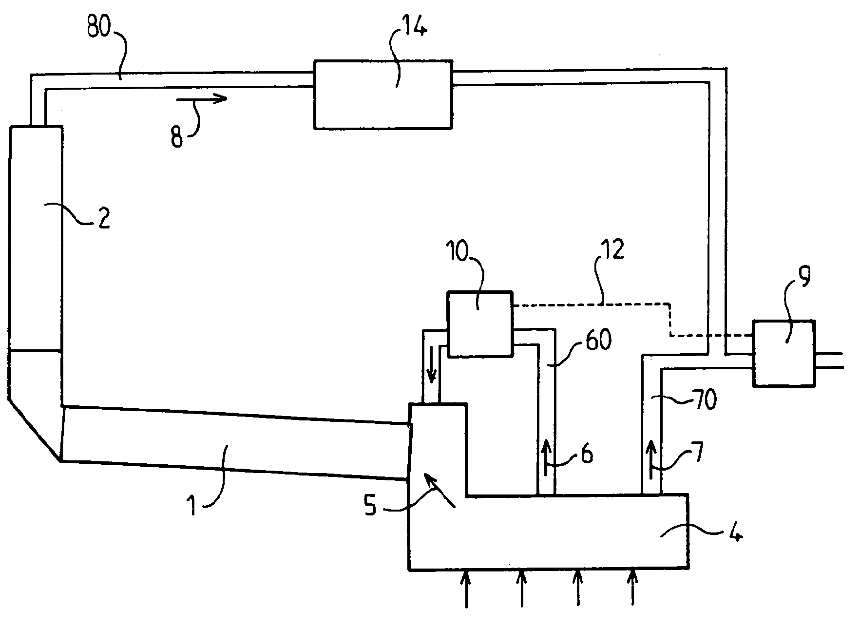
[0084] Consider the plant according to example 2 of the invention, in which 50% of the flue from the cyclone preheater is used to dry the feedstock.

[0085] The preheater plume is split in two. Not used for dry materials, 150000Nm 3 The first partial flow per hour is directed through an exchanger (third exchanger) and lowers the gas from 335°C to 135°C, exchanging 13.1 MW of power. Said switch is connected to two other switches (first switch and second switch), thus having a total power of 28.8 megawatts. The conversion efficiency reached 28%, producing 8.06 megawatts of electricity.

[0086] The marginal efficiency of the additional energy provided by the fuel (ie 9 MW) is 56% compared to Example 1 which has a recoverable energy of 3.02 MW. This value is comparable to the efficiency of modern thermal power plants using solid fuels.


PUM


Abstract

The invention relates to a method for manufacturing a cement clinker in a facility including: - a rotary furnace (1), - a cyclone preheater (2) receiving the fumes from said rotary furnace; - an air blowing clinker cooler (4), and at least one heat exchanger (9), referred to as a first heat exchanger. According to the method of the invention: - the raw materials are preheated and decarbonated in said cyclone preheater (2); - the clinker, coming out of the furnace, is cooled in said clinker cooler (4); a first portion (5) of the hot air generated by said clinker cooler, or so-called secondary air, is directed to the rotary furnace (1) to be used as combustion air; a second portion (6) of the hot air generated in said clinker cooler, or so-called tertiary air, is directed and carried separately from the first portion to a place in the facility where fuel is burned; and a third portion (7) of hot air generated in said clinker cooler, or so-called excess air, is carried into at least said first heat exchanger (9) for the purpose of recovering power to produce electricity. According to the invention, a second heat exchanger (10) coacts with the tertiary air (6) in order to heat a receiving fluid from a fluid circuit (12) common to said first heat exchanger (9) and said second heat exchanger (10). The invention also relates to such a cement clinker manufacturing facility.

Description

technical field [0001] The present invention relates to a method for producing cement clinker in a plant, and a plant for such producing cement clinker. Background technique [0002] The manufacture of cement clinker usually uses the so-called "dry firing" roasting method, in which pre-ground raw materials are calcined in a rotary kiln. In order to reduce the energy requirements for operation, exchangers are added upstream and downstream of the rotary furnace, which directly recover the heat contained in the material and the fumes output from the furnace. Thus, the temperature of the product exiting the furnace exceeds 1000°C, while the temperature of the hot gas stream (air or smoke) exiting these exchangers not used for the roasting operation is usually no more than 350°C. However, these gases also contain a certain amount of heat, which can account for 20 to 30% of the energy introduced into the plant in the form of fuel. [0003] Hot gases are typically used for the dr...

Claims


Application Information

Patent Timeline
IPC IPC(8): F27B7/20F27D17/00C04B7/47
CPCC04B7/475F27B7/2033F27D17/004Y02P40/121
Inventor S.德夫罗S.梅蒂维耶
Owner 菲弗斯有限公司
Features
  • R&D
  • Intellectual Property
  • Life Sciences
  • Materials
  • Tech Scout
  • Unparalleled Data Quality
  • Higher Quality Content
  • 60% Fewer Hallucinations
Learn More