Plasma processing apparatus

A plasma and processing device technology, which is applied in the field of plasma processing devices, can solve problems such as ununiform processing of the treated surface and uneven plasma, and achieve the effects of eliminating metal pollution, reducing usage, and improving versatility

Inactive Publication Date: 2011-05-11
TOKYO ELECTRON LTD +1
View PDF6 Cites 3 Cited by
  • Summary
  • Abstract
  • Description
  • Claims
  • Application Information

AI Technical Summary

Problems solved by technology

[0012] On the other hand, when the conductive surface wave is propagated along the metal surface to excite plasma in the processing container, if the shape and size of the surface wave propagating portion that propagates the microwave around the dielectric body are not uniform, the The plasma excited by the conductor surface wave into the processing container is not uniform
As a result, there is concern that uniform processing cannot be performed on the entire processing surface of the substrate.

Method used


Image

  • Plasma processing apparatus
  • Plasma processing apparatus
  • Plasma processing apparatus

Examples


Deformed example 1

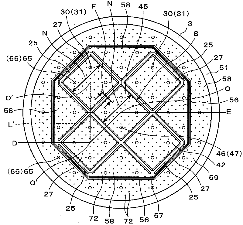
[0207] Figure 15 It is a bottom view of the cover 3 of the plasma processing apparatus 1 according to Modification 1. FIG. In the plasma processing apparatus 1 according to Modification 1, a cover made of, for example, Al 2 o 3 Eight dielectric bodies 25 are formed. Same as before, such as Figure 7 As shown, each dielectric body 25 has a substantially square plate shape. The respective dielectric bodies 25 are arranged such that their apex angles are adjacent to each other. In addition, among the adjacent dielectric bodies 25, the apex corners of the respective dielectric bodies 25 are arranged adjacent to each other on the line L' connecting the center point O'. In this way, eight dielectric bodies are arranged so that their apex angles are adjacent to each other and the apex angles of each dielectric body 25 are adjacent to each other on the line connecting the center points O' of the adjacent dielectric bodies 25. The dielectric body 25 can thereby form a square reg...

Deformed example 2

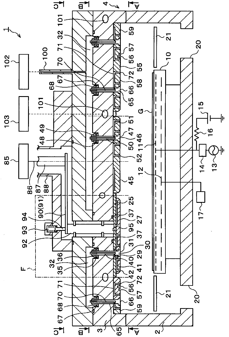
[0220] Figure 16 It is a longitudinal cross-sectional view showing a schematic configuration of a plasma processing apparatus 1 according to Modification 2 ( Figure 17 D-O'-O-E section in). Figure 17 yes Figure 16 A-A sectional view in . In the plasma processing apparatus 1 according to Modification 2, a cover made of, for example, Al 2 o 3 Eight dielectric bodies 25 are formed. Same as before, such as Figure 7 As shown, each dielectric body 25 has a substantially square plate shape. The respective dielectric bodies 25 are arranged such that their apex angles are adjacent to each other. In addition, among the adjacent dielectric bodies 25, the apex corners of the respective dielectric bodies 25 are arranged adjacent to each other on the line L' connecting the center point O'. In this way, eight dielectric bodies are arranged so that their apex angles are adjacent to each other and the apex angles of each dielectric body 25 are adjacent to each other on the line co...

Deformed example 3

[0227] Figure 18 It is a vertical cross-sectional view showing a schematic configuration of a plasma processing apparatus 1 according to Modification 3 ( Figure 19 D-O’-O-E profile in ). Figure 19 yes Figure 18 A-A sectional view in . In the plasma processing apparatus 1 according to Modification 3, a cover made of, for example, Al 2 o 3 Four dielectric bodies 25 are formed. Same as before, such as Figure 7 As shown, each dielectric body 25 has a substantially square plate shape. The respective dielectric bodies 25 are arranged such that their apex angles are adjacent to each other. In addition, among the adjacent dielectric bodies 25, the apex corners of the respective dielectric bodies 25 are arranged adjacent to each other on the line L' connecting the center point O'. In this way, the apex angles of the dielectric bodies 25 are adjacent to each other, and the apex angles of the dielectric bodies 25 are adjacent to each other on the line L' connecting the center ...


PUM


Abstract

The objective is to improve the processing uniformity for a substrate. Disclosed is a plasma processing apparatus equipped with a metallic processing chamber (4) which houses a substrate (G) being processed with plasma, an electromagnetic source (85) which supplies the electromagnetic waves required to excite a plasma in processing chamber (4), and multiple dielectric bodies (25), which transmit the electromagnetic waves supplied by electromagnetic source (85) into the interior of processing chamber (85) and a portion of which are exposed to the interior of processing chamber (4), on the underside of the cover (3) of processing chamber (4). A metal electrode (27) which is electrically connected to the cover (3) is provided on the underside of the dielectric bodies (25). The portion of dielectric bodies (25) exposed between metal electrode (27) and cover (3) form an essentially polygonal shape when viewed from the interior of processing chamber (4). In addition, the multiple dielectric bodies (25) are disposed with the apex angles of the polygonal shapes adjacent to each other, and surface wave propagation parts which propagate electromagnetic waves are arranged on the underside of cover (3) and the underside of metal electrode (27) exposed to the interior of processing chamber (4).

Description

technical field [0001] The present invention relates to a plasma processing apparatus for energizing plasma and applying processing such as film formation to a substrate. Background technique [0002] For example, in a manufacturing process of a semiconductor device, an LCD device, etc., a plasma processing apparatus that excites plasma in a processing container using microwaves and applies CVD processing, etching processing, etc. to a substrate is used. As this plasma processing apparatus, there is known a device in which microwaves are supplied from a microwave source via a coaxial tube or a waveguide to a dielectric body disposed on the inner surface of a processing container, and the energy of the microwaves is used to make the specified energy supplied into the processing container gas plasma. [0003] In recent years, the size of the plasma processing apparatus has gradually increased along with the increase in the size of the substrate and the like. When the dielectr...

Claims


Application Information

Patent Timeline
Patent Type & Authority Applications(China)
IPC IPC(8): H05H1/46H01L21/265H01L21/3065H01L21/31
CPCH01J37/32192H01J37/3222H01J37/32238H05H1/46
Inventor 平山昌树大见忠弘
Owner TOKYO ELECTRON LTD
Why Eureka
Try Eureka