Buffer landing leg for planet detector

A technology of detectors and landing legs, which is applied in the direction of extraterrestrial vehicles, etc., can solve problems such as self-repair, heavy weight, and attitude adjustment, and achieve the effects of long service life, good structural rigidity, and convenient processing

Inactive Publication Date: 2011-05-18
NANJING UNIV OF AERONAUTICS & ASTRONAUTICS
View PDF4 Cites 32 Cited by
  • Summary
  • Abstract
  • Description
  • Claims
  • Application Information

AI Technical Summary

Problems solved by technology

The airbag buffer device rebounded many times and rolled over after landing, and the attitude was not suitable for control, and it was impossible to adjust the attitude, and it was difficult to return from the lunar surface; the hydraulic buffer device required strict sealing and thermal protection measures in a vacuum, and the structure was complex and heavy. Low reliability; compressible energy-absorbing buffer devices mainly use aluminum (or paper) honeycomb structure and honeycomb structure filled with foam molding as buffer materials. The buffer damping performance of aluminum honeycomb buffer is unstable and the force is difficult to control. The disadvantage is that the honeycomb aluminum cannot be recovered after deformation, and the self-repairing function operation cannot be performed on the landing attitude of the detector
The mass of the electromagnetic buffer mechanism is too large, the structure is complex, and it is easily affected by the failure of the power supply system
Magnetorheology is still in the development stage in the aerospace field, and the technology is not mature enough

Method used


Image

  • Buffer landing leg for planet detector
  • Buffer landing leg for planet detector

Examples


Embodiment Construction

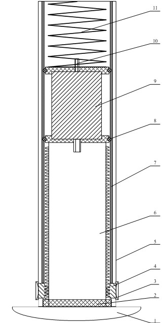
[0014] Such as figure 1 As shown, the buffer landing leg of the planetary probe of the present invention includes an outer cylinder 5, an inner cylinder 6 and a foot pad 1, a guide rail 7 is arranged on the inner wall of the outer cylinder 5, and a rotating motor 9 is arranged on the upper end of the inner cylinder 6. The output rotating shaft 10 of the rotary motor 9 is fixedly connected with the inner cylinder 6, and a compression spring 11 is also arranged on the upper end of the rotary motor, and the upper end of the compression spring 11 contacts with the top of the outer cylinder 5, and the two sides of the rotary motor 9 are also provided with Two sets of 4 pulleys 8; the inner cylinder 6 slides up and down in the outer cylinder 5 through the pulleys 8, the foot pad 1 is arranged at the lower end of the inner cylinder 6, and is connected by a linear bearing 2, and the outer peripheral surface of the inner cylinder 6 is provided with a spiral convex Teeth, on the outer c...


PUM


Abstract

The invention discloses a buffer landing leg for a planet detector, which comprises an outer cylinder, an inner cylinder and a foot cushion, wherein a guide rail is arranged on the inner wall of the outer cylinder, a rotating motor is arranged at the upper end of the inner cylinder, an output rotating shaft of the rotating motor is fixedly connected with the inner cylinder, a compression spring is arranged on the upper end of the rotating motor, the upper end of the compression spring is in contact with the top of the outer cylinder, two sides of the rotating motor are also provided with guide wheels matched with the guide rail; and the foot cushion is arranged at the lower end of the outer cylinder, helical convex teeth are arranged on the outer peripheral surface of the inner cylinder, and a pawl matched with the helical convex teeth is arranged on the outer cylinder and compressed in the helical convex teeth through an external elastic member. The invention has the advantages of no interference in processes of installation and movement of the landing leg mechanism, good structural rigidity, lighter mass, simple structure, convenience of processing, long service life, high reliability and capability of absorbing higher impact energy and realizing self-repairing function of buffer postures.

Description

technical field [0001] The invention belongs to a reusable buffer landing leg for a planetary probe, and the landing leg can realize the self-repairing function of the buffer attitude. Background technique [0002] The buffer mechanism is the key and core component of the soft lander of the planetary probe. The selection and design of the buffer and energy-absorbing components is the key to whether the soft lander can achieve a stable, reliable and safe soft landing. Its main function is to absorb the impact energy generated by the planetary probe during the landing impact, and avoid excessive impact loads acting on the probe and the experimental equipment it carries to cause damage. [0003] At present, the planetary probe lander buffer devices that have been adopted abroad include airbag buffer devices, compressible energy absorbers, air pressure buffer devices, hydraulic buffer devices, magnetorheological buffer devices, electromagnetic damping buffer devices and mechanic...

Claims


Application Information

Patent Timeline
Patent Type & Authority Applications(China)
IPC IPC(8): B64G1/16
Inventor 聂宏林轻陈金宝柏合民徐磊
Owner NANJING UNIV OF AERONAUTICS & ASTRONAUTICS
Why Eureka
Try Eureka