Eureka AIR delivers breakthrough ideas for toughest innovation challenges, trusted by R&D personnel around the world.

PCB (Printed Circuit Board) insulation resistance testing jig

An insulation resistance test and PCB board technology, applied in the field of test racks, can solve the problems of ink, substrate insulation performance degradation, encountering other metal objects, test results deviation, etc., to improve test efficiency, reduce the risk of electric shock, operation handy effect

Inactive Publication Date: 2011-05-18
SHENNAN CIRCUITS
View PDF4 Cites 21 Cited by
  • Summary
  • Abstract
  • Description
  • Claims
  • Application Information

AI Technical Summary

Problems solved by technology

[0003] 1) During the process of soldering copper wires on the test point of the PCB, the ink and plate around the test point will be subjected to high temperature impact of welding, which will reduce the insulation performance of the ink and the substrate itself, resulting in deviations in the test results;
[0004] 2) Flux will be used in the process of soldering copper wires. When the flux is not wiped clean, it will directly affect the test data, resulting in inaccurate data, which cannot reflect the real insulation performance of the PCB board;
[0005] 3) It takes a lot of time and effort to prepare copper wires, solder, remove flux after soldering, and comb copper wires, and the efficiency is low;
[0006] 4) Since the soldered copper wires are exposed and soft, if they are not combed properly, they may touch other metal objects, which may cause electric shock

Method used


Image

  • PCB (Printed Circuit Board) insulation resistance testing jig
  • PCB (Printed Circuit Board) insulation resistance testing jig
  • PCB (Printed Circuit Board) insulation resistance testing jig

Examples


Embodiment Construction

[0027] In order to describe the technical content, structural features, achieved goals and effects of the present invention in detail, the following will be described in detail in conjunction with the embodiments and accompanying drawings.

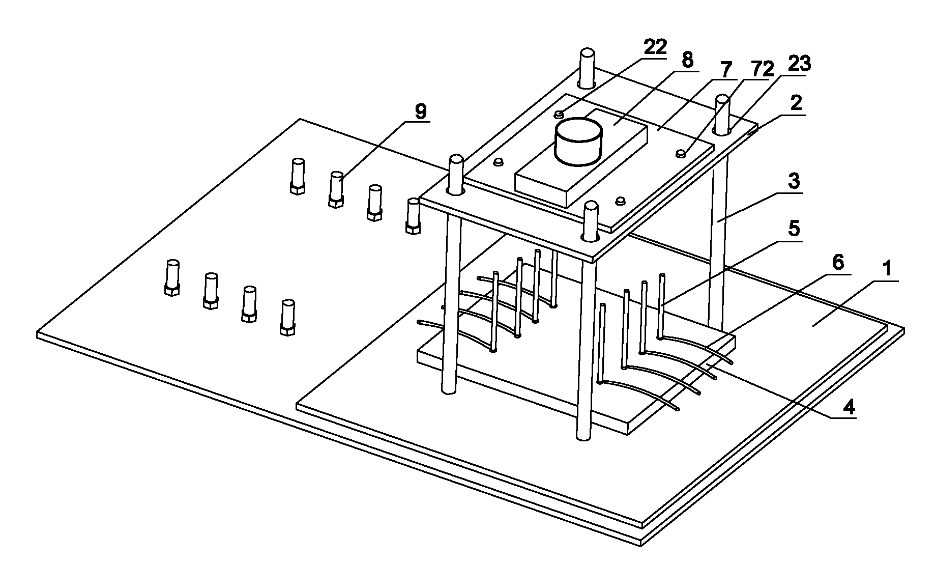
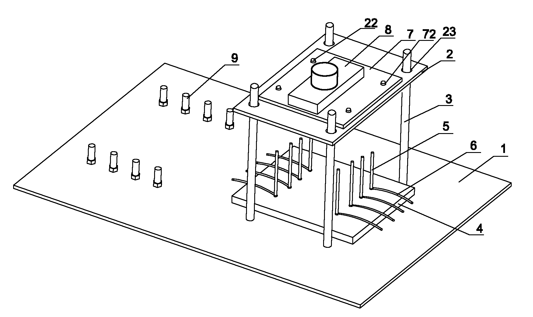
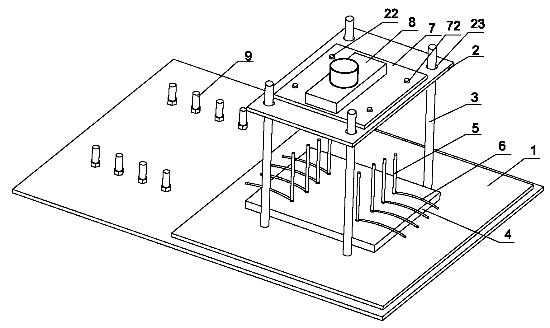
[0028] As the first embodiment of the PCB insulation resistance test frame of the present invention, please refer to figure 1 , including a base 1, a PCB board placement platform 2, a guide post 3, a test pin 5, a test pin stand 4, a test lead 6, a terminal post 9 and a counterweight 8, the guide post 3 is four in number, and is fixedly arranged on The four corners of the base 1, the PCB board placement platform 2 is fixedly arranged on the base 1, the test needle platform 4 is located above the PCB board placement platform 2, and corresponds to the position of the PCB board placement platform 2 up and down, and the test needle platform 4 is A guide hole 41 matched with the guide column 3 is provided, the test needle platform 4 slides up a...


PUM


Abstract

The invention relates to a testing jig, in particular to a PCB (Printed Circuit Board) insulation resistance testing jig, comprising a base, a PCB placing table, guide posts, test pins, a test pin table and test leads. The guide posts and the PCB placing table or the test pin table are fixed on the base, the PCB placing table is provided with a PCB locating structure, the test pins are arranged on the test pin table, the PCB placing table or the test pin table is provided with guiding holes matched with the guide posts, and the test leads electrically connect the guide posts and the test pins. In the invention, the PCB insulation resistance testing jig is a special jig, which avoids the steps of lead preparation, lead welding, soldering flux cleaning and the like in the prior art, improves the test efficiency, and prevents the high-temperature impingement on the PCB and the poor influence of the soldering flux on the tested results in the test lead welding process.

Description

technical field [0001] The invention relates to a test frame, in particular to a PCB insulation resistance test frame. Background technique [0002] During or after the PCB board is manufactured, an insulation resistance test is required to determine whether the insulation performance of the PCB board is qualified. The current test method for the insulation resistance of the PCB board is: determine several test points on each PCB board, and test Spot weld the copper wires, and realize the connection between the PCB board and the test equipment through the soldered wires, so as to achieve the purpose of testing the insulation resistance of the PCB board. The problem that prior art exists is: [0003] 1) During the process of soldering copper wires at the test point of the PCB board, the ink and plate around the test point will be subjected to the high-temperature impact of welding, which will reduce the insulation performance of the ink and the substrate itself, resulting in...

Claims


Application Information

Patent Timeline
Patent Type & Authority Applications(China)
IPC IPC(8): G01R1/04G01R27/02
Inventor 王鹏牛玉鹏
Owner SHENNAN CIRCUITS
Why Eureka
Eureka Blog
Learn More