Attached insulator body cleaning device

A technology for cleaning devices and insulators, applied in cleaning methods and appliances, cleaning methods using tools, chemical instruments and methods, etc., can solve the problems of the insulation performance of the insulator body, the impact of power transmission safety, time-consuming and labor-intensive efficiency, etc., to improve Endurance, reduced replacement or charging times, and improved cleaning efficiency

Inactive Publication Date: 2017-08-29
DONGYING POWER SUPPLY COMPANY STATE GRID SHANDONG ELECTRIC POWER +2
View PDF6 Cites 0 Cited by
  • Summary
  • Abstract
  • Description
  • Claims
  • Application Information

AI Technical Summary

Problems solved by technology

In the early years, the insulator body was mostly used for utility poles. Later, with the development, it was slowly used for high-voltage wire connection towers. Many disc-shaped insulators are hung on one end of the tower. It is to increase the creepage distance, usually made of glass or ceramics. Our country has a vast territory, and the environment in many regions is relatively harsh. Sand and dust conditions will generate deposits on the surface of the insulator body. The deposits may be conductive. In the case of dense deposits, the insulation performance of the insulator body may be affected. The safety of transportation has a great impact, so the accumulation on the insulator body should be cleaned regularly. However, the existing cleaning methods for the volume of the insulator body are mainly manual cleaning, which is time-consuming and labor-intensive and inefficient.

Method used


Image

  • Attached insulator body cleaning device
  • Attached insulator body cleaning device
  • Attached insulator body cleaning device

Examples


Embodiment Construction

[0015] The present invention will be further described in detail below in conjunction with the accompanying drawings and specific embodiments.

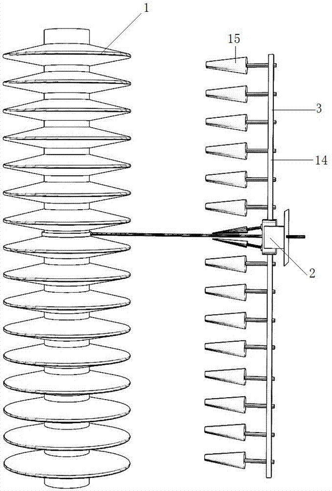
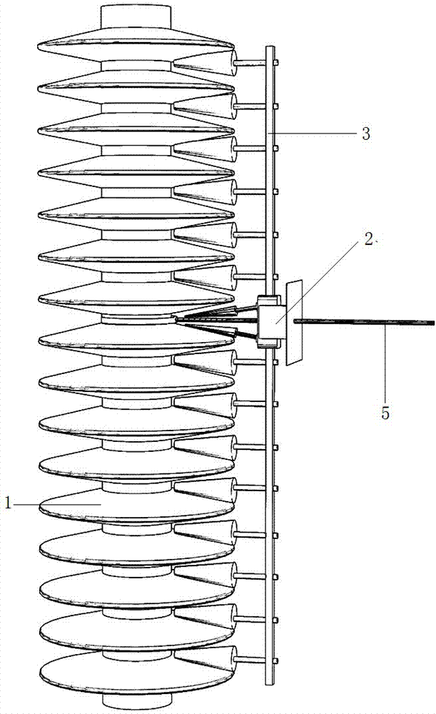
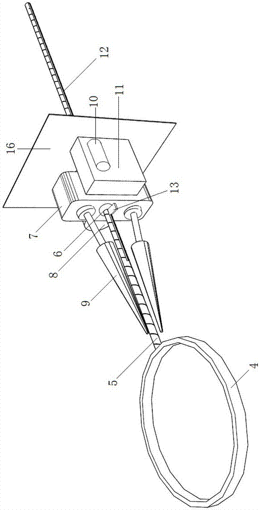
[0016] Such as Figure 1-3 As shown, the attached insulator body cleaning device includes an insulator body 1, an active cleaning unit 2, and a follower cleaning unit 3; the active cleaning unit 2 includes a support ring 4 that surrounds the middle of the insulator body 1 and is rotatably connected with the insulator body 1, a fixed On the outer surface of the support ring 4 and the threaded rod 5 arranged perpendicular to the axial direction of the insulator body 1, the screw sleeve 6 threadedly connected with the threaded rod 5; the screw sleeve 6 is rotatably mounted on the base 7; the base 7 is installed with Screw sleeve driving motor 8, two rollers 9 symmetrically arranged about the threaded rod 5, the roller driving motor 10, the gear box 11 connected with the output end of the roller driving motor 10; the output end of the scr...


PUM


Abstract

The invention discloses an attachment-type insulator body cleaning device, and relates to the technical field of maintenance of electrical equipment used in transformer substations. The attachment-type insulator body cleaning device comprises an insulator body, a driving cleaning unit and a follow-up cleaning unit; the driving cleaning unit comprises a support ring, a screw rod and a screw barrel; the support ring encircles the middle part of the insulator body and is connected with the insulator body in a rotary manner; the screw rod is fixedly arranged on the outer side surface of the support ring and is arranged in a manner of being vertical to the axial direction of the insulator body; the screw barrel is in threaded connection with the screw rod; the screw barrel is arranged on a base in a rotary manner; a screw barrel driving motor, two rollers, a roller driving motor and a speed-changing gear box are arranged on the base; the two rollers are symmetrically arranged about the screw rod; the speed-changing gear box is connected with the output end of the roller driving motor; the follow-up cleaning unit comprises a cross beam, of which the middle part is fixed on the base; and the cross beam is uniformly provided with hairbrushes which are separately matched with umbrella skirt-shaped clearances of the insulator body. The attachment-type insulator body cleaning device can rotate along the radial direction of the insulator body to clean the surface of the insulator body; the cleaning effect is good; and the labor intensity of transformer substation maintenance personnel is lowered.

Description

technical field [0001] The invention relates to the technical field of power equipment maintenance for substations. Background technique [0002] The insulator body is a special insulation control that can play an important role in overhead transmission lines. In the early years, the insulator body was mostly used for utility poles. Later, with the development, it was slowly used for high-voltage wire connection towers. Many disc-shaped insulators are hung on one end of the tower. It is to increase the creepage distance, usually made of glass or ceramics. Our country has a vast territory, and the environment in many regions is relatively harsh. Sand and dust conditions will generate deposits on the surface of the insulator body. The deposits may be conductive. In the case of dense deposits, the insulation performance of the insulator body may be affected. The safety of transportation is greatly affected, so the accumulation on the insulator body should be removed regularly....

Claims


Application Information

Patent Timeline
Patent Type & Authority Patents(China)
IPC IPC(8): B08B1/04
CPCB08B1/04
Inventor 胡永伟刘泽昆昝乐宋学龙杨西建李钊
Owner DONGYING POWER SUPPLY COMPANY STATE GRID SHANDONG ELECTRIC POWER
Why Eureka
Try Eureka