
Field calibration and precision measurement method for spot laser measuring system

A measurement system and field calibration technology, applied in measurement devices, optical devices, image data processing, etc., can solve the problems of harsh calibration conditions and complicated calibration steps.

Inactive Publication Date: 2011-05-18
JIANGNAN UNIV
View PDF0 Cites 48 Cited by
  • Summary
  • Abstract
  • Description
  • Claims
  • Application Information

AI Technical Summary

Problems solved by technology

[0005] The purpose of the present invention is to overcome the shortcomings of the traditional point laser measurement system, such as harsh calibration conditions and cumbersome calibration steps, and propose a flexible, high-precision, fast-speed, good stability, strong real-time performance, simple method, small amount of calculation, and universal Calibration and measurement technology for robust point laser systems

Method used

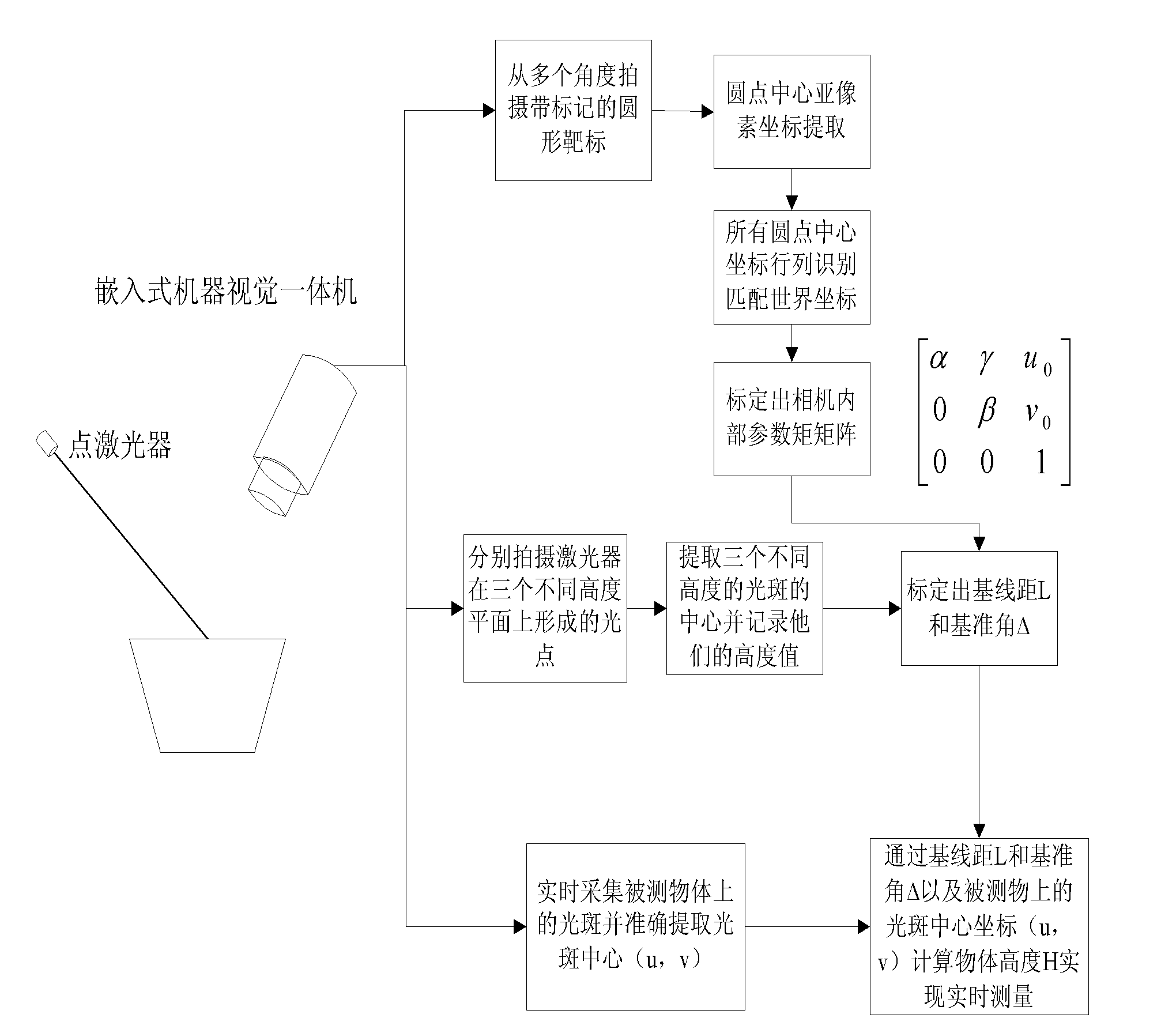
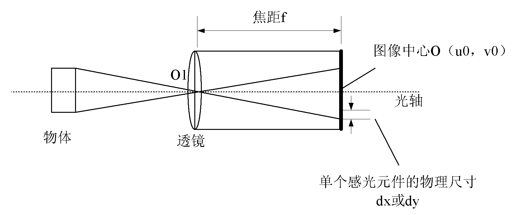

Image

  • Field calibration and precision measurement method for spot laser measuring system
  • Field calibration and precision measurement method for spot laser measuring system
  • Field calibration and precision measurement method for spot laser measuring system

Examples


Embodiment Construction

[0044] In order to improve the flexibility and practicability of the laser measurement system and improve the measurement accuracy, the invention develops a calibration technology. The calibration technology algorithm has small code size, fast operation speed, high precision, strong real-time performance, and good stability. It can improve the disadvantages of traditional measurement, reduce costs, and increase production speed.

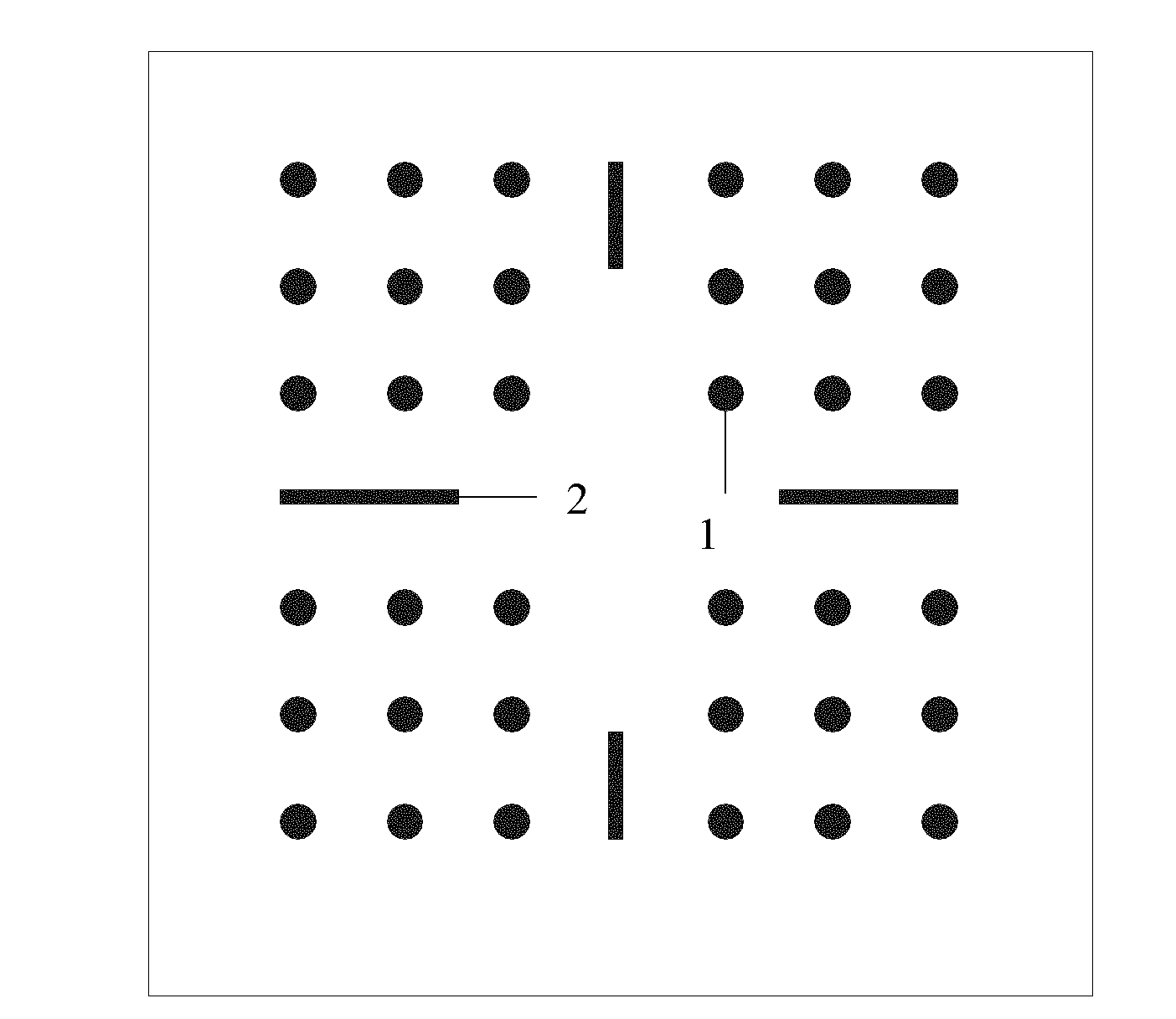
[0045] The present invention utilizes as image 3 The marked circular target shown, including dot 1 and marking strip 2, can realize fast positioning of corner points, automatically realize the recognition of rows and columns of corner points, and automatically match the world coordinates and pixel coordinates of corner points, which is beneficial to the camera Automated parameter calibration; analyze the mathematical model of the laser-camera measurement system, introduce the concepts of baseline distance and reference angle, and only need to shoot ...


PUM


Abstract

The invention provides a simple and flexible field calibration and precision measurement method for a spot laser measuring system by analyzing the camera imaging principle, establishing a camera imaging model and introducing the concepts of two structural parameters, namely a basic line distance and a reference angle aiming at the defects of extreme calibration conditions and complicated calibration steps of the traditional spot laser-camera measuring system. In the method, only two standard planar heights H1 and H2 are needed to precisely complete the calibration task of the system structure, and the spot laser-camera measuring system of the algorithm has higher measuring precision so as to meet the requirement of precision measurement. The algorithm makes the spot laser-camera structure adjustable and field calibration of system structural parameters possible; and the flexibility of a laser ranging system is greatly improved and the method has important significance for actual vision measurement.

Description

technical field [0001] The invention relates to a point laser on-site calibration and measurement method, in particular to a point laser visual precision measurement method that can be used for on-site calibration and debugging. Background technique [0002] With its advantages of fast speed, high precision, non-contact and high degree of automation, visual measurement technology has played an increasingly important role in the field of non-contact measurement in recent years. Visual measurement can not only replace a lot of manual work, improve the level of production automation, improve monitoring accuracy, but also an effective solution when many conventional measurement methods cannot be realized. [0003] Calibration (including camera parameter calibration and system structure parameter calibration) is a very critical and important link in the visual measurement system. The accuracy of the calibration results and the stability and real-time performance of the algorithm ...

Claims


Application Information

Patent Timeline
IPC IPC(8): G06T7/00G01B11/03G06T7/80
Inventor 白瑞林孟伟
Owner JIANGNAN UNIV
Learn More