Composite micro wind turbine generator

A kind of wind power generator, composite technology, applied in the direction of generator/motor, piezoelectric effect/electrostrictive or magnetostrictive motor, electromechanical device, etc., can solve the problem of low generator output power, low conversion efficiency, It cannot meet the piezoelectric requirements of wireless sensor network nodes and other problems, and achieve the effect of increasing output power, simple structure, and convenient batch processing

Inactive Publication Date: 2011-05-18
CHONGQING UNIV
View PDF4 Cites 19 Cited by
  • Summary
  • Abstract
  • Description
  • Claims
  • Application Information

AI Technical Summary

Problems solved by technology

The current micro-vibrating wind turbines only use one of electromagnetic induction, piezoelectric effect and electro

Method used


Image

  • Composite micro wind turbine generator
  • Composite micro wind turbine generator
  • Composite micro wind turbine generator

Examples


Embodiment Construction

[0025] At the same time, based on the principle of piezoelectric effect and electromagnetic induction, the composite micro-wind generator that realizes electromechanical conversion is composed of micro-stents, micro-beams, piezoelectric structures, metal coils, permanent magnets and bases. The micro-beams are fixed on the micro-stents, and the piezoelectric The structure and metal coils are processed on the micro-beams, and the permanent magnets are fixed on the base. The following is a typical process for making a composite micro-wind turbine:

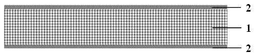
[0026] 1. Select a double-sided polished silicon wafer as the substrate 1, and grow S on the front and back of the substrate 1 simultaneously by oxidation or low-pressure chemical vapor deposition i o 2 Layer 2, such as figure 1 shown;

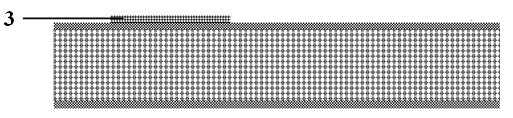
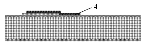
[0027] 2. Deposit Ti and Pt layers sequentially on the front side of the silicon wafer by magnetron sputtering, then apply photoresist, and perform photolithography once to form a photoresist patter...


PUM


Abstract

The invention discloses a composite micro wind turbine generator, which comprises a micro bracket, a micro beam, a piezoelectric structure, a metal coil, a permanent magnet and a base, wherein one end or two ends of the micro beam are fixed on the micro bracket; the micro bracket is fixed on the base; and the micro beam, the piezoelectric structure and the metal coil form the movable part of the composite micro wind turbine generator. The micro beam is provided with the piezoelectric structure and the metal coil, the permanent magnet is fixed on the base, the south pole or north pole of the permanent magnet is opposite to the plane of the metal coil, a gap is preserved between the permanent magnet and the plane of the coil, and the generator converts the energy of vibration of a micro structure into electric energy by using both a piezoelectric effect and the principle of electromagnetic interaction and has a higher mechanical-electric conversion efficiency than micro wind turbine generators using the piezoelectric effect or the principle of electromagnetic interaction alone. The composite micro wind turbine generator can be processed in batches by silicon micromachining technology at low cost and is particularly suitable for supplying power to wireless sensor network nodes and the like.

Description

technical field [0001] The invention belongs to the field of micro-electro-mechanical systems (MEMS), in particular to MEMS micro-energy (Power MEMS) technology for converting environmental wind energy into electric energy. Background technique [0002] Compared with traditional energy sources such as batteries, micro-energy sources that directly convert vibration energy, fluid kinetic energy, thermal energy, solar energy, etc. kind of power supply. Based on micro-electromechanical systems (MEMS) technology, MEMS micro-energy, which converts environmental physical energy into electrical energy, also has many advantages such as small size, maintenance-free, and easy integration, and has become one of the hotspots of micro-energy research in the world. [0003] The micro-wind generator based on the wind-induced vibration mechanism converts the environmental wind energy into micro-structure vibration energy by using the micro-structure vibration caused by wind load, and furthe...

Claims


Application Information

Patent Timeline
IPC IPC(8): H02N2/18H02K35/00
Inventor 贺学锋杜志刚印显方高军温志渝
Owner CHONGQING UNIV
Why Eureka
Try Eureka