Eureka AIR delivers breakthrough ideas for toughest innovation challenges, trusted by R&D personnel around the world.

Heat dissipating device

A technology of heat dissipation device and heat pipe, which is applied to indirect heat exchangers, heat exchange equipment, heat exchanger fixing and other directions, can solve the problems of loose buckle fastening, increased material cost and manufacturing cost, short circuit of circuit board, etc. Eliminates risk of board shorts and reduces assembly and material costs

Inactive Publication Date: 2011-05-18
FURUI PRECISE COMPONENT (KUNSHAN) CO LTD +1
View PDF6 Cites 1 Cited by
  • Summary
  • Abstract
  • Description
  • Claims
  • Application Information

AI Technical Summary

Problems solved by technology

[0003] After the radiator is installed, the buckle cannot play any role, which increases the material cost and manufacturing cost, and the buckle may not be tightly fastened due to improper assembly, especially when the buckle is made of metal, it will fall off. Risk of shorting circuit boards

Method used


Image

  • Heat dissipating device
  • Heat dissipating device
  • Heat dissipating device

Examples


Embodiment Construction

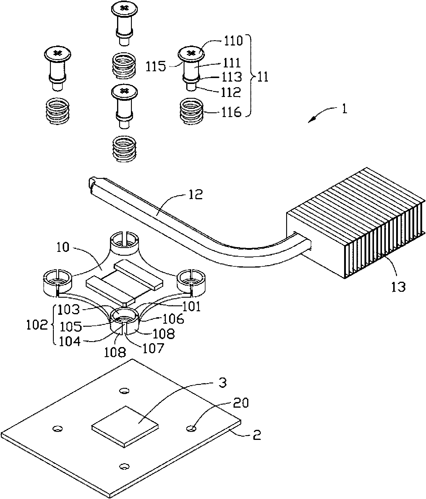
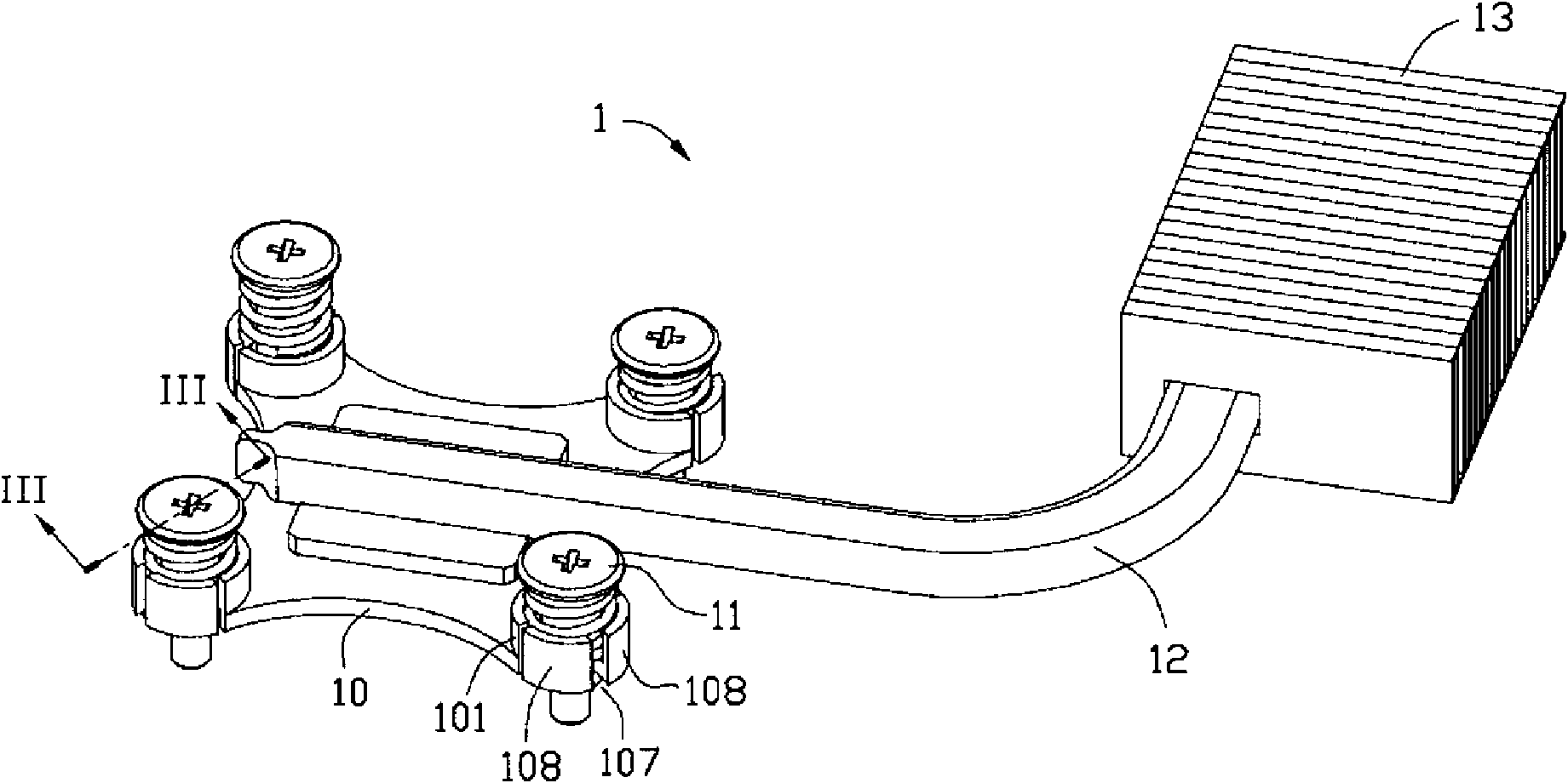
[0010] The heat dissipation device 1 will be further described below with reference to the accompanying drawings. Such as figure 1 As shown, the heat dissipation device 1 includes a base 10 , a plurality of spring fasteners 11 , a heat pipe 12 and a heat sink set 13 . One end of the heat pipe 12 is laid on the upper surface of the base 10 , and the other end passes through the heat sink assembly 13 . The heating electronic components 3 on the circuit board 2 are attached to the lower surface of the base 10 . The base 10 absorbs the heat emitted by the heating electronic components 3 , and the heat pipe 12 transfers the heat from the base 10 to the heat sink group 13 to be dissipated into the air.

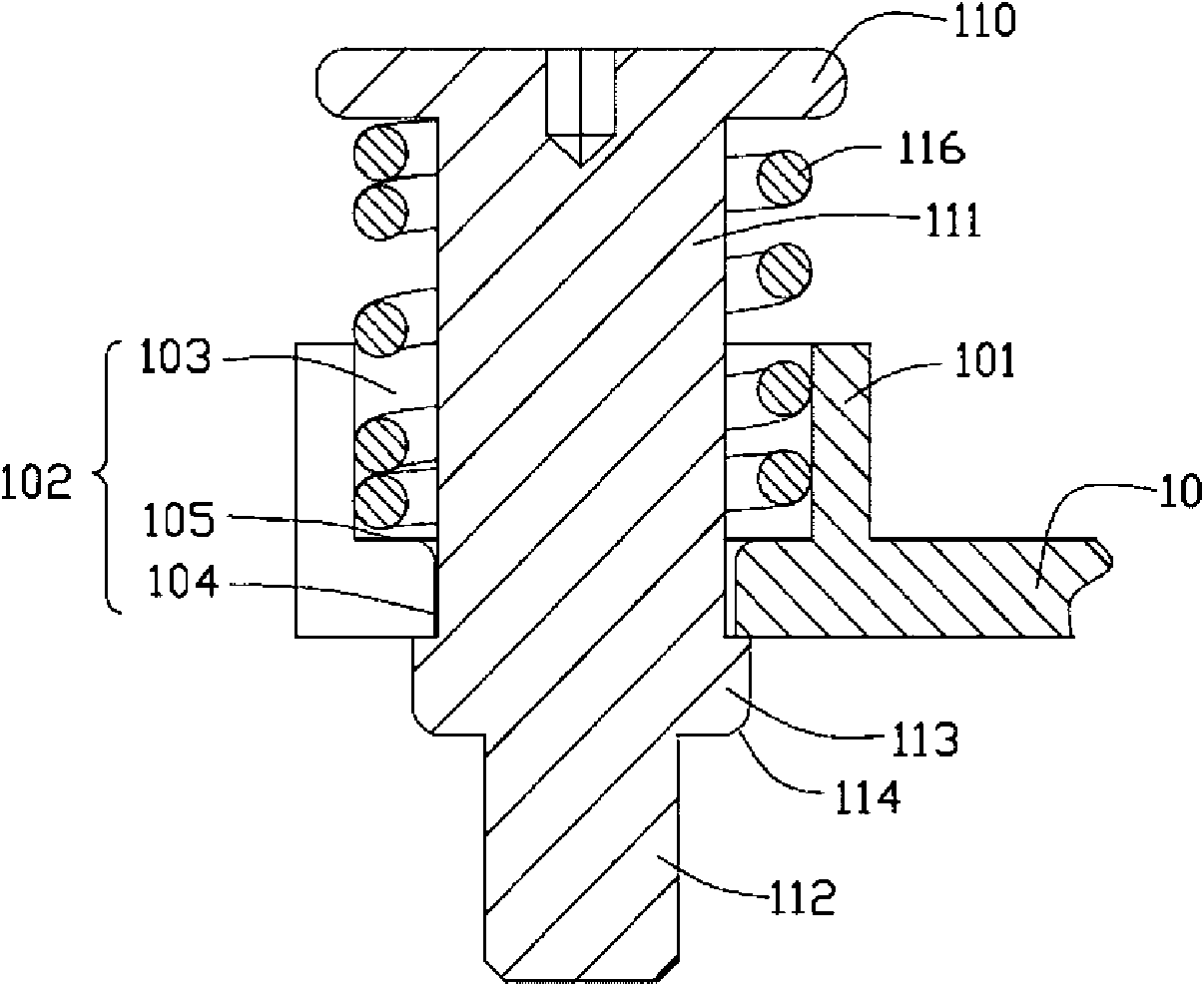
[0011] Please also refer to figure 2 image 3 In this embodiment, the spring fastener 11 is a spring screw. The spring fastener 11 includes a head 110 , a rod body 111 and a spring 116 . The bottom end of the rod body 111 is provided with a thread 112 . The thread 112 of the s...


PUM


Abstract

The invention relates to a heat dissipating device. The heat dissipating device comprises a base and at least one spring fastener, wherein the base is provided with a stepped hole through which the spring fastener passes; an opening is axially formed on the hole wall; the opening divides the hole wall into two elastic arms which are mutually spaced; an annular bulge is formed at the periphery of a rod body; the annular bulge of the rod body extrudes the small hole of the stepped hole to make the two elastic arms of the hole wall expanded outwards and elastically deformed; the annular bulge passes through the small hole of the stepped hole and leans against the bottom of the step of the stepped hole; and the two elastic arms of the hole wall recover elastic deformation to make a spring clamped between the head of the spring fastener and the step of the stepped hole at the same time. Compared with the prior art, the heat dissipating device makes the fastener structure formed by the elastic arms on the base and the annular bulge replace a cramp ring, lowers the cost of a cramp ring assembly and materials and eliminates the risk of short circuits of circuit boards caused by the falling of the cramp ring.

Description

technical field [0001] The invention relates to a heat dissipation device, in particular to a heat dissipation device for heating electronic components. Background technique [0002] At present, with the rapid development of the computer industry, more and more heat is generated by heat-generating electronic components such as micro-processing chips. In order to dissipate the excess heat effectively, the existing method is to attach a radiator on the surface of the heating electronic component to dissipate the heat generated by the heating electronic component, and fix the radiator on the circuit board with spring screws. A plurality of through holes are arranged on the heat sink, through which threads of the spring screws pass through, and are threadedly connected with the threaded holes on the circuit board. For the convenience of transportation, the spring screw is usually pre-assembled with the radiator through the buckle, so that it will not be separated from the radia...

Claims


Application Information

Patent Timeline
Patent Type & Authority Applications(China)
IPC IPC(8): H05K7/20H01L23/40G06F1/20
CPCH01L23/4006H01L23/427F28D15/0233F28F2275/08H01L2924/0002H01L2924/00
Inventor 邱鸿年
Owner FURUI PRECISE COMPONENT (KUNSHAN) CO LTD
Why Eureka
Eureka Blog
Learn More