
Soldering material and electronic component assembly

A technology for soldering materials and electronic components, applied in the direction of welding/cutting media/materials, welding media, electrical components, etc., can solve problems such as disconnection and poor connection, achieve excellent thermal fatigue resistance, reduce poor connection, high resistance Effect of Thermal Fatigue Properties

Inactive Publication Date: 2011-05-18
PANASONIC CORP
View PDF5 Cites 11 Cited by
  • Summary
  • Abstract
  • Description
  • Claims
  • Application Information

AI Technical Summary

Problems solved by technology

The Cu-Sn intermetallic compound 65a has a hard and brittle property, forming a fragile joint interface between the Cu-Sn intermetallic compound 65a and the solder parent phase 65b, and the crack 67 propagates through the continuous phase of the solder parent phase 65, eventually causing Disconnected, bad connection occurred

Method used


Image

  • Soldering material and electronic component assembly
  • Soldering material and electronic component assembly
  • Soldering material and electronic component assembly

Examples


Embodiment

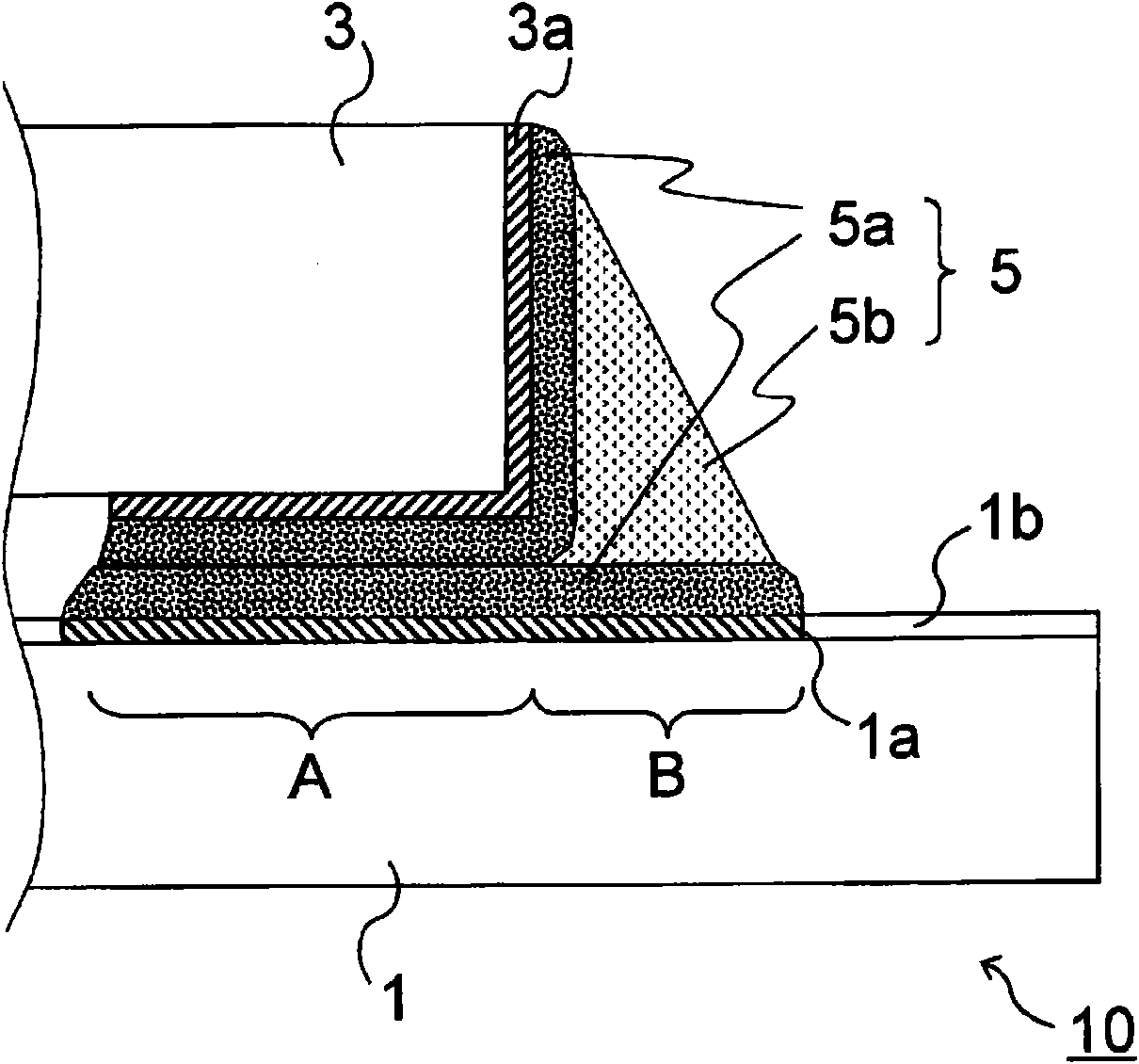
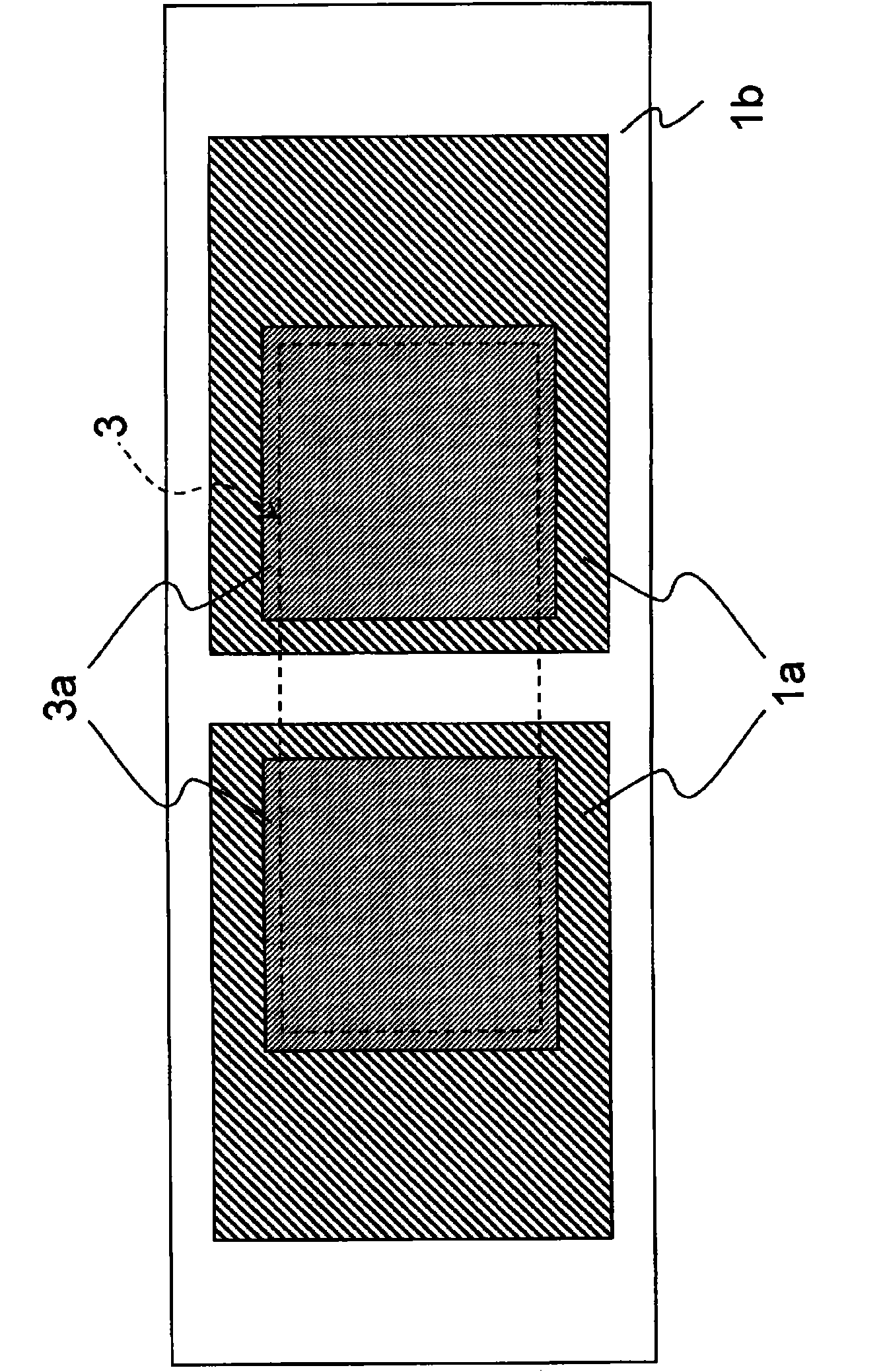
[0113] Use solder materials with various metal compositions shown in Tables 2 and 3, refer to Figure 6 (a) According to the above process flow, it is produced under the following conditions figure 1 The electronic component assembly shown. In Tables 2 and 3, "Bal." represents a balance (Balance).

[0114] Substrate 1: High Tg type high heat-resistant substrate R-1755T, copper clad on both sides, thickness 1.2mm (manufactured by Panasonic Electric Works Co., Ltd.)

[0115] Electrode pad 1a: Cu pad, thickness 35 μm, surface treated with pre-flux treatment agent (Tough-Ace, manufactured by Shikoku Chemical Industry Co., Ltd.)

[0116] Resist 1b: High heat-resistant resist (manufactured by Taiyo Ink Manufacturing Co., Ltd.)

[0117] Electronic part 3: Chip capacitor 1005 size (C1005 manufactured by TDK Corporation)

[0118] Electrode part 3a: Cu electrode (C1005 manufactured by TDK Corporation)

[0119] Mounting method: reflow soldering (after preheating from 150°C to 170°C...


PUM

PropertyMeasurementUnit
melting pointaaaaaaaaaa
thicknessaaaaaaaaaa

Abstract

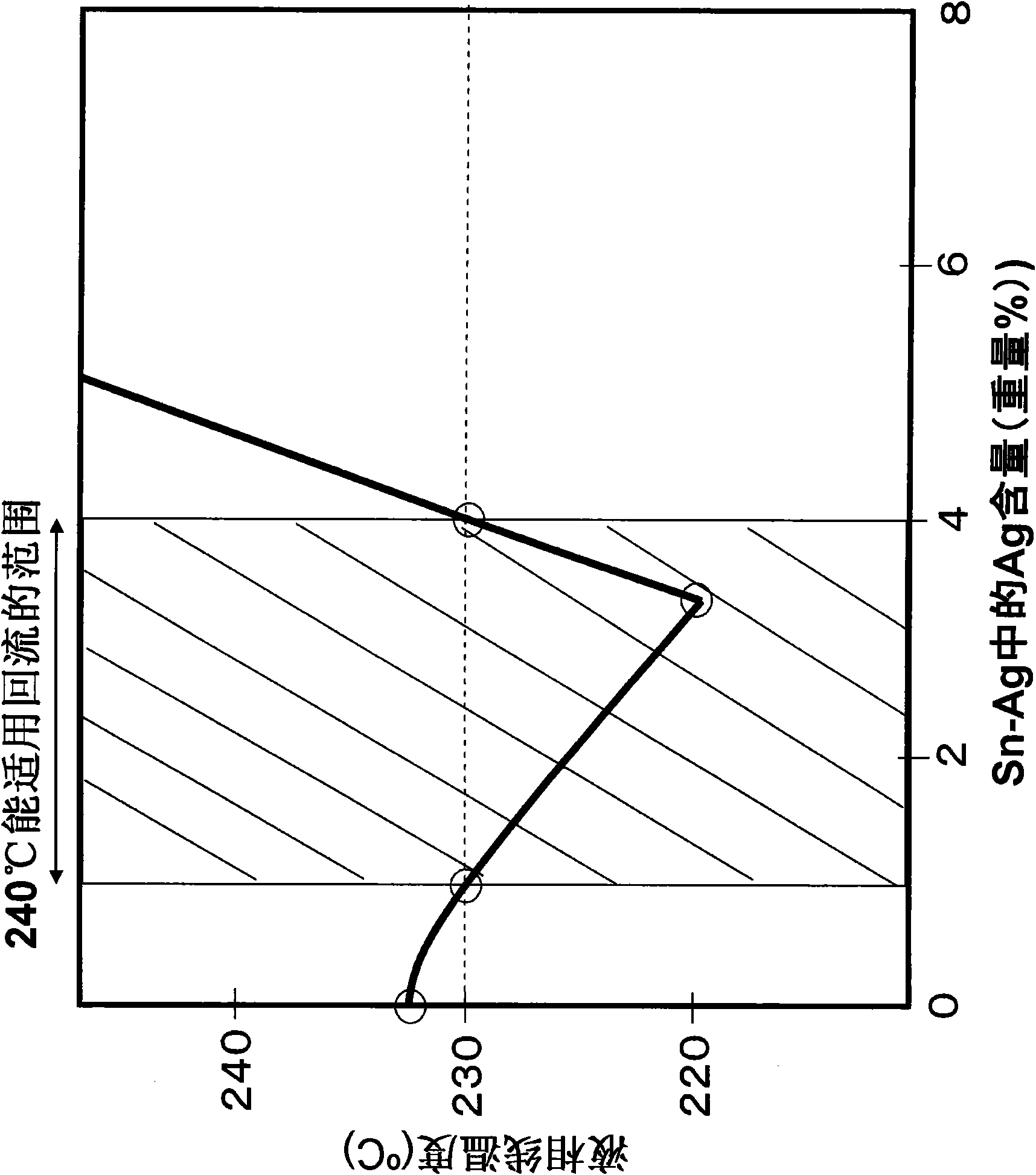
The present invention provides a lead-free soldering material which shows high thermal fatigue resistance and with which it is possible to effectively reduce the occurrence of connection failures that cause a function of a product to stop. The soldering material comprises 1.0-4.0 wt.% Ag, 4.0-6.0 wt.% In, 0.1-1.0 wt.% Bi, up to 1 wt.% (excluding 0 wt.%) the sum of one or more elements selected from a group consisting of Cu, Ni, Co, Fe, and Sb, and Sn as the remainder. When a copper-containing electrode part (3a) of an electronic component (3) is bonded to a copper-containing electrode land (1a) of a substrate (1) with this soldering material, a part (5b) having excellent stress relaxation properties can be formed in the soldering area and a Cu-Sn intermetallic compound (5a) can be rapidly grown from the electrode land (1a) and the electrode part (3a) to form a tenacious blocking structure. Thus, even in a severe temperature environment, cracks can be prevented from generating and propagating and high thermal fatigue resistance can be attained. The occurrence of connection failures can hence be reduced.

Description

technical field [0001] The present invention relates to a lead-free solder material, an electronic component assembly using the solder material, and a method for manufacturing the electronic component assembly. [0002] In addition, in this specification, in order to explain the metal composition of the solder material, a numerical value or a numerical range may be indicated before a metal element other than Sn. % by weight in the metal composition, and the balance is composed of Sn. Background technique [0003] When mounting electronic components on a substrate, they are usually joined by soldering, which is excellent in electrical connectivity and high in productivity and workability. [0004] As a solder material, lead-containing Sn-Pb eutectic solder is currently being used, but as a material to replace Sn-Pb eutectic solder, various lead-free solders have been introduced and researched and put into practical use. [0005] At present, Sn-0.7Cu, Sn-3.0Ag-0.5Cu, Sn-3.5A...

Claims


Application Information

Patent Timeline
Patent Type & Authority Applications(China)
IPC IPC(8): B23K35/26C22C13/00H05K3/34
CPCB23K35/262C22C13/00H05K3/3463H05K2201/10992B32B15/01B23K2201/36H05K3/3442B23K2101/36Y02P70/50
Inventor 酒谷茂昭古泽彰男末次宪一郎中村太一
Owner PANASONIC CORP
Learn More