Engine fuel injection control device

A technology of fuel injection and control device, which is applied in the directions of fuel injection control, engine control, machine/engine, etc., can solve problems such as feedback control can not keep up, the air-fuel ratio is too rich, and the too rich becomes larger, etc., to improve the startability, The effect of preventing engine speed fluctuations and expanding the feedback control area

Active Publication Date: 2016-07-06
HONDA MOTOR CO LTD
View PDF6 Cites 0 Cited by
  • Summary
  • Abstract
  • Description
  • Claims
  • Application Information

AI Technical Summary

Problems solved by technology

[0006] In the air-fuel ratio control device described in Patent Document 1, feedback control is prohibited until the engine speed drops to a predetermined value during deceleration, and feedback control is started after the engine speed drops below a predetermined value. Therefore, in the feedback control When the engine is decelerating suddenly at the beginning, the feedback control process will not be able to keep up with the sharp drop in engine speed, so the air-fuel ratio will easily enter an over-rich state
Furthermore, as described above, when the valve clearance is generated due to carbon, the possibility of over-riching becomes higher, so there is a problem that the area where feedback control can be appropriately performed is reduced.

Method used


Image

  • Engine fuel injection control device
  • Engine fuel injection control device
  • Engine fuel injection control device

Examples


Embodiment Construction

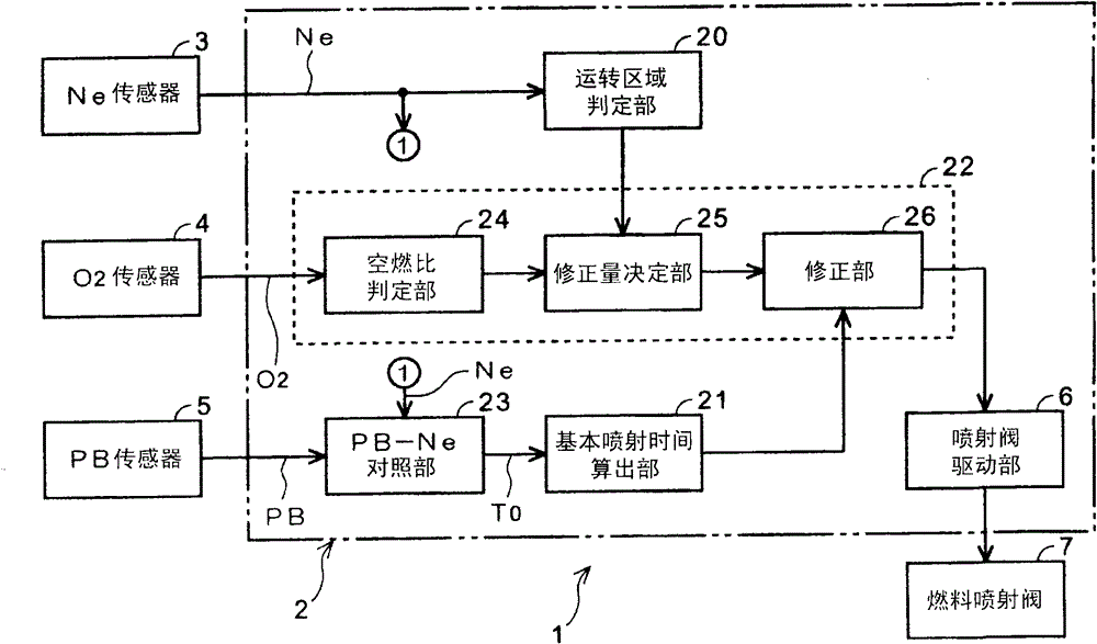
[0035] Hereinafter, an embodiment of the present invention will be described with reference to the drawings. figure 1 It is a block diagram showing a system configuration of a fuel injection control device according to an embodiment of the present invention, and particularly a configuration diagram showing control in an idling region that is a low rotation speed region. In this figure, the fuel injection control device 1 is installed in an internal combustion mechanism, ie, an engine, which is a drive source of a motorcycle or the like. The fuel injection control device 1 includes: a control unit 2 functioning as a fuel injection amount determination unit; an engine speed sensor (hereinafter referred to as “Ne sensor”) 3 for detecting an engine speed Ne; An oxygen concentration sensor (hereinafter referred to as "O2 sensor") 4 functioning as a concentration detecting means, and a negative pressure sensor (hereinafter referred to as "PB sensor") 5 for detecting an intake negati...


PUM


Abstract

The invention provides a fuel injection control device for an engine. A correction amount determination unit (25) determines a correction amount (KO2) for correcting the basic fuel injection timing based on the oxygen concentration in the exhaust gas so that the air-fuel ratio of the engine converges to the stoichiometric air-fuel ratio. A correction unit (26) calculates a fuel injection timing using a correction amount (KO2). The correction amount (KO2) is calculated by adding and subtracting a correction term to a reference correction amount. An operating range determination unit (20) determines whether the engine speed (Ne) is in an idling range (A) lower than a predetermined speed, or in a (B) range above a predetermined speed. The correction amount determination unit (25) uses a predetermined time after the engine speed range shifts from the (B) region to the (A) region as the correction term in the (A) region, and uses a second correction term larger than the second correction term in the (B) region. Calculate the correction amount (KO2) of the first correction term. When the engine speed rapidly enters the idling region, it is possible to prevent the tendency of the air-fuel ratio to become too rich due to the delay of the correction value update process caused by the O2 feedback.

Description

technical field [0001] The present invention is used in a fuel injection control device for an engine, particularly a fuel injection control device for an engine including feedback control that converges an intake air-fuel mixture to a stoichiometric air-fuel ratio based on the oxygen concentration in exhaust gas. Background technique [0002] In recent years, from the point of view of fuel consumption and exhaust gas composition restriction (emission restriction), a feedback control has been implemented in which the oxygen concentration in the exhaust gas is detected by an oxygen sensor installed in the exhaust system, and based on the detected value The calculated correction amount converges the intake air-fuel mixture to an appropriate air-fuel ratio, that is, the stoichiometric air-fuel ratio. Generally, this kind of feedback control is performed in the vicinity of an idle rotation speed, that is, in a low rotation speed region, where the fuel injection amount is determi...

Claims


Application Information

Patent Timeline
Patent Type & Authority Patents(China)
IPC IPC(8): F02D41/30F02D41/12
Inventor 远藤惠太宇津木克洋渡边二夫田岛克树田中弘志
Owner HONDA MOTOR CO LTD
Why Eureka
Try Eureka