
Underwater active electric field imaging device

An imaging device and electric field technology, applied in measuring devices, radio wave measurement systems, radio wave reflection/re-radiation, etc., can solve problems affecting underwater vision, underwater TV work restrictions, underwater TV can not work normally, etc. problem, to achieve the effect of simple hardware

Inactive Publication Date: 2011-05-25
UNIV OF ELECTRONICS SCI & TECH OF CHINA
View PDF4 Cites 14 Cited by
  • Summary
  • Abstract
  • Description
  • Claims
  • Application Information

AI Technical Summary

Problems solved by technology

However, in a turbid water body with a large amount of suspended matter, the light will be scattered and reflected by the suspended matter in the water, which will affect the underwater vision and make the underwater TV unable to work normally.
With the deepening of marine resource exploration and marine resource development, the working environment of underwater vehicles is becoming more and more complex: for underwater vehicles working in the offshore, due to the inland river sediment and nutrient-rich substances flowing into the ocean, many shallow seas are turbid water bodies. Underwater TV work is extremely limited
For underwater vehicles used in the fields of marine underwater archaeology, marine resource exploration, deep-sea scientific investigation, and maintenance of submarine oil wells, on the one hand, there are a large number of plankton in the deep sea; on the other hand, when the submersible approaches the target, due to The movement of the submersible will stir the silt near the target to make the water turbid, which also affects the effect of underwater TV close-range imaging

Method used


Image

  • Underwater active electric field imaging device
  • Underwater active electric field imaging device
  • Underwater active electric field imaging device

Examples


Embodiment 1

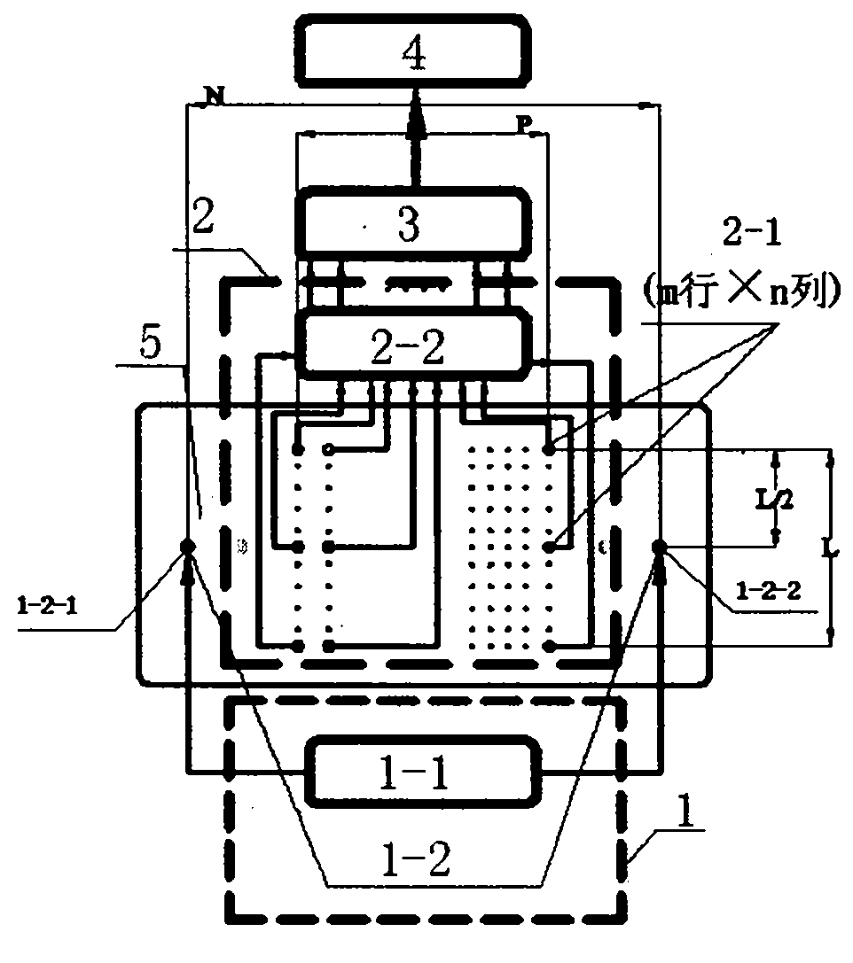
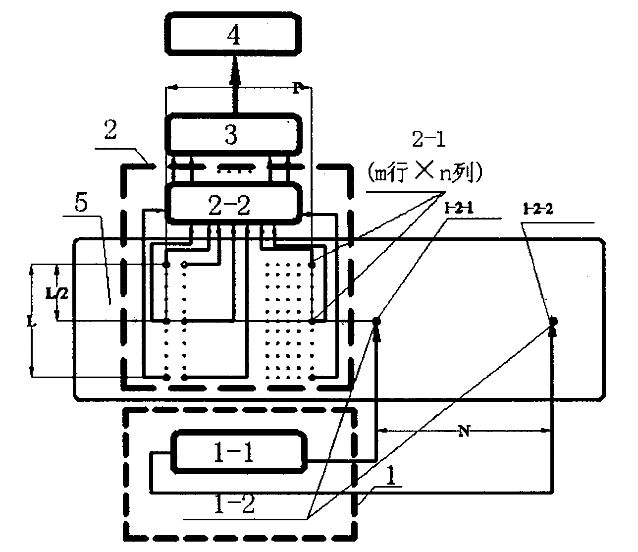
[0022] Such as Figure 5 As shown, in the conductive liquid medium 5, the positions of the transmitting electrode 1-2 and the receiving electrode 2-1 are fixed on a circuit board. The target body 6 can move relative to the medium in the liquid medium 5 (translation and rotation). The signal generator 1-1 generates a DC or sine or square wave signal as an excitation source, which is input to the emitting electrode 1-2. A regularly changing electric field is formed in the medium. The current received by the receiving electrode 2-1 will change accordingly. The signal is transformed by the receiving circuit 2-2, amplified and converted into an analog voltage signal, and finally converted into a digital signal by the data sampler 3 and entered into the data processor 4 for processing. When there is a target in the electric field in the liquid medium, the magnitude of the current change of the receiving electrode will vary with the relative position between the object and the rece...

Embodiment 2

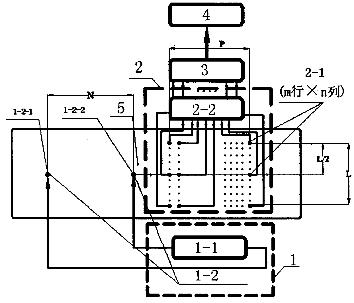
[0024] Such as Image 6 As shown, the position of the target body 6 in the liquid medium 5 is fixed. In the liquid medium 5 , the transmitting electrode 1 - 2 and the receiving electrode 2 - 1 are fixed on a fixed plate 7 . The fixed plate 7 can relatively move (translate or rotate) in the medium. The DC or sinusoidal or square wave signal generated by the signal generator is used as an excitation source and input to the emitting electrodes 1-2. A regularly changing electric field is formed in the medium. The current received by the receiving electrode 2-1 will change accordingly. The signal is transformed by the receiving circuit 2-2, amplified and converted into an analog voltage signal, and finally converted into a digital signal by the data sampler 3 and entered into the data processor 4 for processing. When there is a target in the electric field, the amplitude of the current change of the receiving electrode will change, and the amplitude of the current change will ch...


PUM


Abstract

The invention relates to an underwater active electric field imaging device belonging to the technical field of underwater imaging. The underwater active electric field imaging device comprises a transmitter 1, a receiver 2, a data sampler 3 and a data processor 4, wherein the transmitter comprises a signal generator (1-1) and a transmitting electrode (1-2); and the receiver comprises a receiving electrode (2-1) and a receiving circuit (2-2). The underwater active electric field imaging device has the advantages that: 1, the device carries out imaging through detecting the variation of an electric field so that the problem that the visual field of optical imaging is limited is solved; 2, the device has simple hardware structure and high energy efficiency and can solve the problem of complicated acoustic imaging hardware; and 3, the device can reflect the geometrical characteristics and the distance characteristics of target bodies.

Description

technical field [0001] The invention is an underwater imaging device. In particular, it relates to an underwater active electric field imaging device and belongs to the technical field of underwater detection and imaging. Background technique [0002] Entering the 21st century, the objects of human exploration have shifted from the land to the ocean, which accounts for 71% of the earth's surface area, and extends from shallow waters to deep seas. Underwater vehicles have become an important tool for human exploration of the ocean. How underwater vehicles image the surrounding environment in the dark environment of the ocean to perceive the surrounding underwater environment has become an urgent problem to be solved. Underwater imaging technology has become one of the key technologies for the functionalization and practicality of deep sea underwater vehicles. It is used for underwater vehicles to perceive the surrounding environment in the dark underwater environment. At ...

Claims


Application Information

Patent Timeline
Patent Type & Authority Applications(China)
IPC IPC(8): G01S13/89
Inventor 彭杰钢王世杰
Owner UNIV OF ELECTRONICS SCI & TECH OF CHINA
Learn More