
Drive control method for glow plugs

A technology of glow plug and electronic control unit, which is applied in engine control, combustion method, electrical control, etc., can solve the problems of shortening the life of ceramic glow plug, deterioration of ceramic heater, deterioration of exhaust gas characteristics, etc., to suppress harmful components, The effect of avoiding cracks and improving reliability

Inactive Publication Date: 2011-05-25
BOSCH CORP
View PDF2 Cites 0 Cited by
  • Summary
  • Abstract
  • Description
  • Claims
  • Application Information

AI Technical Summary

Problems solved by technology

[0005] However, when such a ceramic glow plug is driven by the conventional driving method, in the state where the cooling condition in the combustion chamber is severe, that is, in the state where the eddy current cooling is strong, the surface portion of the ceramic heater and the There is a large temperature difference between the interior of the buried heating body, and the ceramic heater is degraded due to the large thermal stress. In the worst case, an annular crack occurs inside the ceramic heater, which may cause the ceramic The life of the glow plug is shortened, which has been confirmed by the inventors of the present application
[0006] However, the cause of the above-mentioned cracks is not clear, and the current situation is that by limiting the maximum temperature of the ceramic glow plug, the possibility of cracks in the worst case can only be avoided, which leads to deterioration of exhaust gas characteristics at low temperatures, misfires, etc. Further defects such as increased engine noise caused by the frequent occurrence of ceramic glow plugs lead to the problem that the original strengths of ceramic glow plugs cannot be fully utilized

Method used


Image

  • Drive control method for glow plugs
  • Drive control method for glow plugs
  • Drive control method for glow plugs

Examples


Embodiment Construction

[0027] Below, refer to Figure 1 to Figure 5 Embodiments of the present invention will be described.

[0028] In addition, members, arrangements, and the like described below do not limit the present invention, and various changes can be made within the scope of the gist of the present invention.

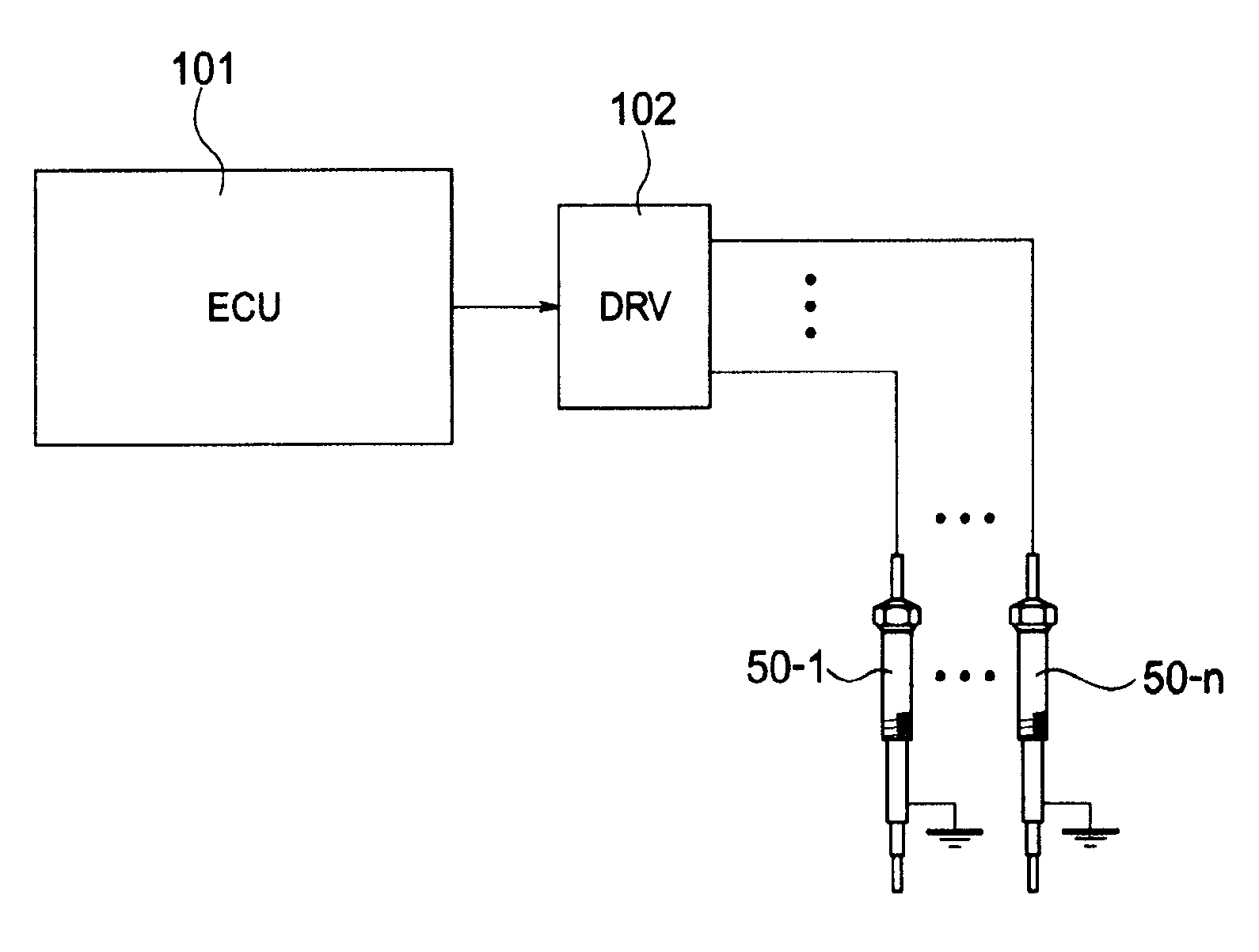
[0029] First, refer to figure 1 A configuration example of a glow plug drive control device to which the glow plug drive control method in the embodiment of the present invention is applied will be described.

[0030] The glow plug driving device in the embodiment of the present invention is roughly divided into electronic control units ( figure 1 denoted as "ECU") 101, and energized circuit ( figure 1 Denoted as "DRV") 102 and constituted.

[0031] The electronic control unit 101 is centered on, for example, a microcomputer (not shown) having a well-known and well-known configuration, has memory elements (not shown) such as RAM and ROM, and has a circuit for transmitting signal...


PUM


Abstract

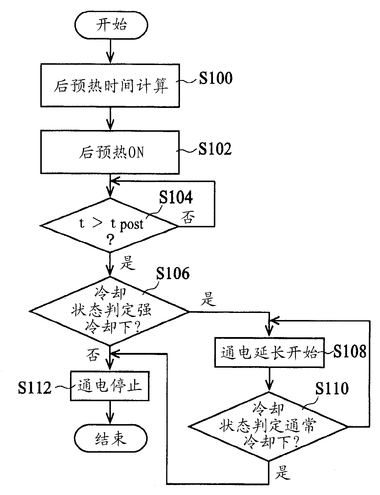
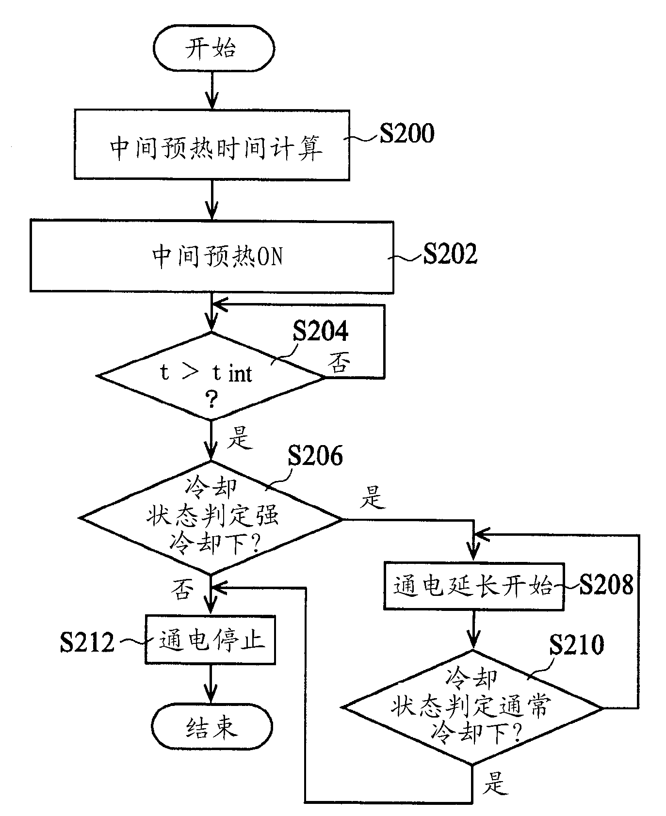
This drive control method for glow plugs suppresses deterioration caused by thermal stress without sacrificing the necessary maximum temperature. When the period of post glow of ceramic glow plugs (50-1 to 50-n) ends, if it is judged that the cooled state in the combustion chamber of an engine has not reached a predetermined highly cooled condition for a first predetermined time or longer, power supply for the post glow is stopped (S106, S112), whereas if it is judged that the cooled condition in the combustion chamber of the engine has reached the predetermined highly cooled condition for the first predetermined time or longer, a predefined map of post-glow-extending voltages is used to obtain the voltage for extending the post glow power supply, extension of the power supply is started using the voltage, and subsequently, when it is judged that the cooled state in the combustion chamber of the engine is transitioning to a state in which the predetermined highly cooled condition has abated over a second predetermined time or longer, extension of the post glow power supply is stopped (S108, S110), thereby easing thermal stress and suppressing deterioration of the ceramic heater.

Description

technical field [0001] The present invention relates to a method of driving and controlling a glow plug mainly used for starting assistance of a diesel engine, and more particularly, to a method of driving and controlling a glow plug for improving reliability due to relaxation of thermal stress. Background technique [0002] Conventionally, as the driving control of the glow plug of the vehicle, the energization control based on the so-called PWM control is generally performed to cope with the rapid temperature rise. Furthermore, countermeasures are also taken in that, in view of various changes in the cooling state of the glow plug throughout the entire operating range of the engine, in order to realize a more appropriate driving state while being exposed to the various cooling states, a The drive voltage correction map of the glow plug is created using various factors such as the outside air temperature, engine speed, engine drive torque, and air pressure as parameters, an...

Claims


Application Information

Patent Timeline
Patent Type & Authority Applications(China)
IPC IPC(8): F23Q7/00
CPCF02P19/026F02D2200/101F02P19/021F02D2041/0015
Inventor 田中有仁赵艰丰岛康夫
Owner BOSCH CORP
Learn More