Horizontal type spiral centrifuge

A horizontal screw and centrifuge technology, which is applied to centrifuges and centrifuges with rotating drums, etc., can solve the problems of operator inconvenience, damage to mud viscosity and density, and failure to achieve cleaning, etc., to achieve good cleaning effect, The mud pressure is stable and the vibration reduction effect is good

Inactive Publication Date: 2011-06-01
朱士荣
View PDF0 Cites 11 Cited by
  • Summary
  • Abstract
  • Description
  • Claims
  • Application Information

AI Technical Summary

Problems solved by technology

[0002] In the process of using the known horizontal spiral centrifuge, on the one hand, due to the flexible connection between the foot of the centrifuge and the chassis, and the connection part uses rubber gaskets to reduce vibration, after working for a period of time, extreme vibration occurs between the centrifuge and the chassis. Large vibration, loud noise and damage to mechanical parts; on the other hand, because the screw pump supplies slurry to the centrifuge and the centrifuge discharge speed is inconsistent, the mud pressure inside the drum is too high, and the hard and large objects in the drum The propeller blades in the drum cause deformation and damage, and in severe cases, damage the differential gear, which directly affects the service life and quality of the centrifuge; third, when the centrifuge stops working, when cleaning the inside of the drum, the cleaning If the amount of water is small, the purpose of cleaning cannot be achieved. When the amount of cleaning is large, because the cleaning water directly enters the mud, the viscosity and density of the mud are destroyed, so that the drill pipe cannot be lubricated. Fourth, due to the control of the centrifuge speed The motor cannot adjust the speed arbitrarily, generally only has 1-2 speed values, which cannot adapt to the change of geological structure and requires the centrifuge speed to change accordingly; fifth, because the centrifuge works in a relatively harsh environment, and the operator It must be operated on site, which brings great inconvenience to the operator

Method used


Image

  • Horizontal type spiral centrifuge
  • Horizontal type spiral centrifuge

Examples


Embodiment Construction

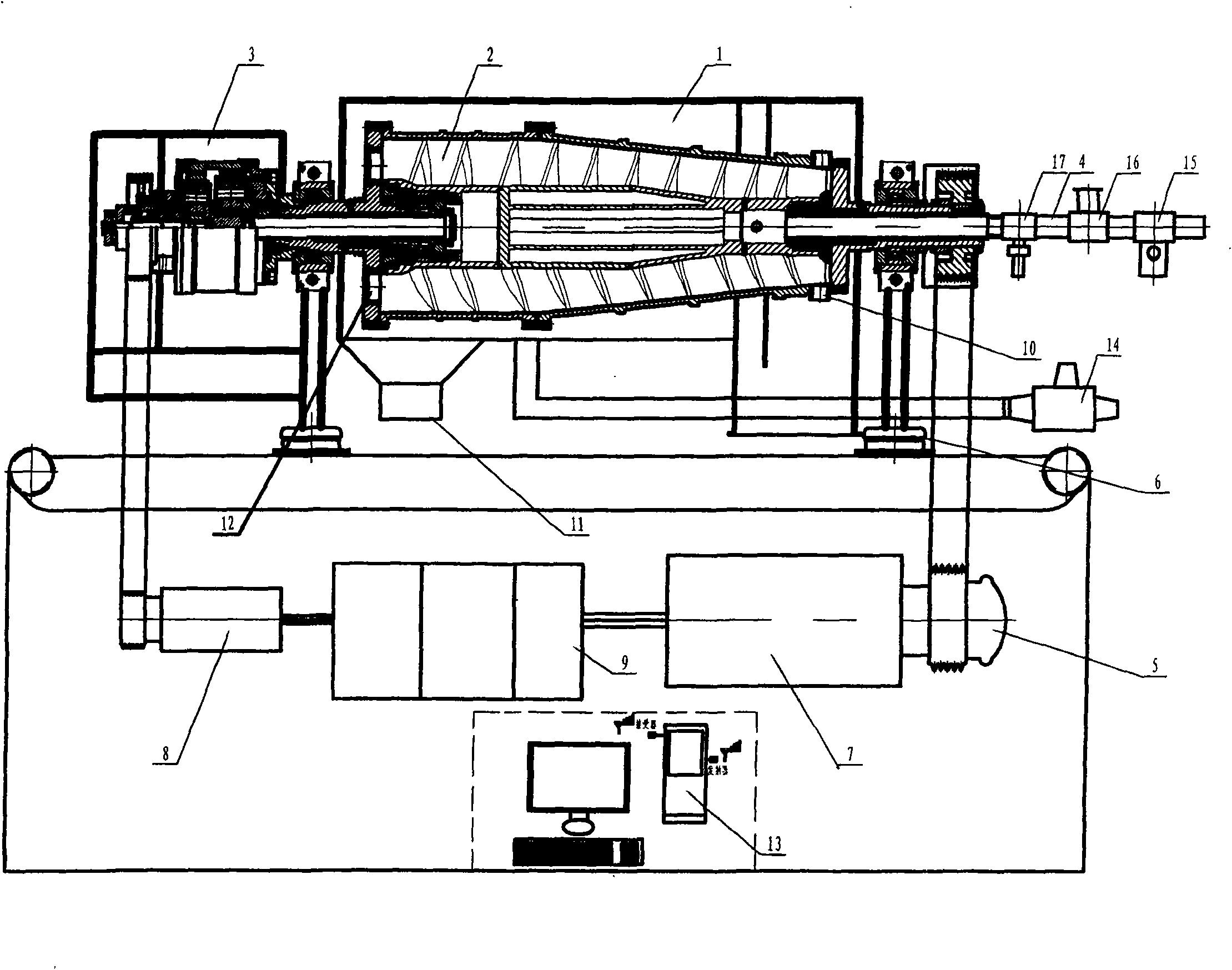
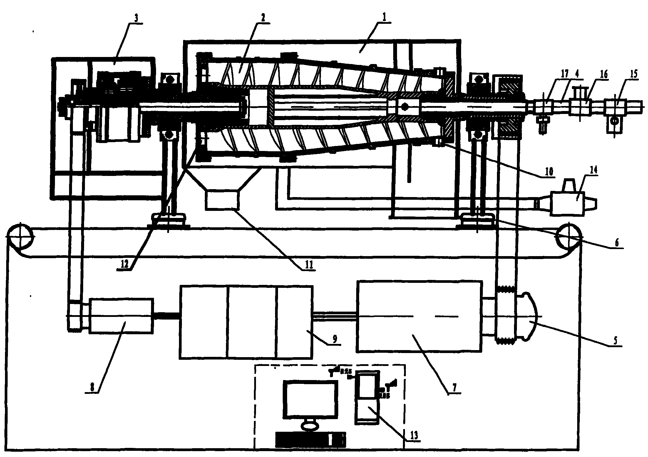
[0008] If the present invention is used in oil field drilling (as shown in the accompanying drawings), the open end of the constant pressure liquid flow valve 15 is connected with the screw pump, and the slurry inlet valve 16 is opened, and the frequency conversion control 9 is instructed to work through the wireless remote sensing device 13, The frequency conversion control 9 directs the main motor 7 and the auxiliary motor 8 to work respectively. The main motor 7 drives the drum 1 to rotate, and the auxiliary motor 8 drives the screw propeller 2 and the drum 1 to rotate at different speeds and in the same direction through the differential assembly 3 . When the screw pump pumps the drilling mud into the inner cavity of the drum 1, due to the pushing action of the blades of the screw propeller 2, the barite, stones and large-grained hard objects in the mud are discharged from the slag discharge port 10. After being discharged, the remaining mud that meets the drilling pipe lu...


PUM


Abstract

The invention relates to a horizontal type spiral centrifuge, which is provided with a pressure-constant slurry overflow valve on the end of a slurry inlet pipe of a commonly used horizontal type centrifuge, so as to ensure the stable pressure of the slurry in a rotary drum, wherein a slurry and water separating valve is arranged on the end of a slurry outlet pipe, for solving the problem that the slurry viscosity and intensity of the slurry are influenced by washing the centrifuge with too much clean water; a specific compound vibration-attenuation base is arranged between a machine leg and a chassis, for solving the problem that the noise and the damaged parts are caused by the vibration of the centrifuge; a frequency-conversion control master motor or main and secondary motors are used for solving the problem that the demands on the rotation speed of the main and secondary motors are different on different lands; and a wireless remote sensing device is used for realizing the remote control and convenient operation.

Description

technical field [0001] The invention relates to a horizontal screw centrifuge, which is suitable for making lubricating and cooling mud machinery used in the drilling process, and belongs to the field of machinery manufacturing. Background technique [0002] In the process of using the known horizontal spiral centrifuge, on the one hand, due to the flexible connection between the foot of the centrifuge and the chassis, and the connection part uses rubber gaskets to reduce vibration, after working for a period of time, extreme vibration occurs between the centrifuge and the chassis. Large vibration, loud noise and damage to mechanical parts; on the other hand, because the screw pump supplies slurry to the centrifuge and the centrifuge discharge speed is inconsistent, the mud pressure inside the drum is too high, and the hard and large objects in the drum The propeller blades in the drum cause deformation and damage, and in severe cases, damage the differential gear, which dir...

Claims


Application Information

Patent Timeline
Patent Type & Authority Applications(China)
IPC IPC(8): B04B3/04B04B11/02B04B7/00B04B9/10B04B13/00
Inventor 朱士荣
Owner 朱士荣
Why Eureka
Try Eureka