Module combined type exhaust-heat boiler

A waste heat boiler and module combination technology, applied in the field of boilers, can solve the problems of large floor space, difficult maintenance, complex structure of waste heat recovery and utilization devices and waste gas treatment and utilization devices, etc., to reduce the frequency of failures, facilitate installation, disassembly and adjustment, Improve the effect of difficult maintenance

Inactive Publication Date: 2011-06-01
SHANGHAI NENGCHUANG SCI TECH
View PDF3 Cites 13 Cited by
  • Summary
  • Abstract
  • Description
  • Claims
  • Application Information

AI Technical Summary

Problems solved by technology

[0010] This patent transforms the submerged arc furnace by adding a waste heat recovery and utilization device and a waste gas treatment and utilization device to the submerged arc furnace in the prior art, but the patent still has complex structures of the waste heat recovery and utilization device and the waste gas treatment and utilization device, and the waste heat boiler It is troublesome to install and difficult to maintain, and the design structure of this patent has nothing to do with the present invention
[0011] To sum up, the various waste heat boilers in the prior art, due to the constraints under the technical conditions, lead to the problem of their layout direction, resulting in a large heating area and a large occupied area. However, various improvements in the prior art It is only a change to the accessories of the waste heat boiler, and no improvement is made to its main structure, which makes the installation and maintenance of the integrated design of the waste heat boiler in the prior art troublesome, and it is used for submerged arc furnaces. Due to the above reasons, waste heat boilers are more prone to failures such as tube explosion, water leakage, overheating and burning, and even explosion accidents in severe cases.

Method used


Image

  • Module combined type exhaust-heat boiler
  • Module combined type exhaust-heat boiler
  • Module combined type exhaust-heat boiler

Examples


Embodiment 1

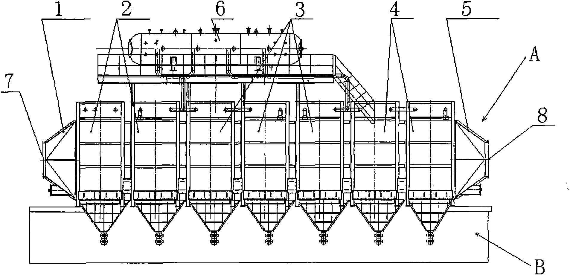
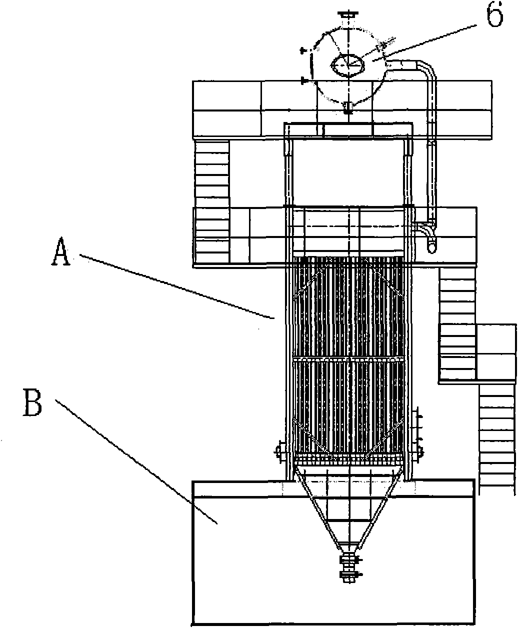
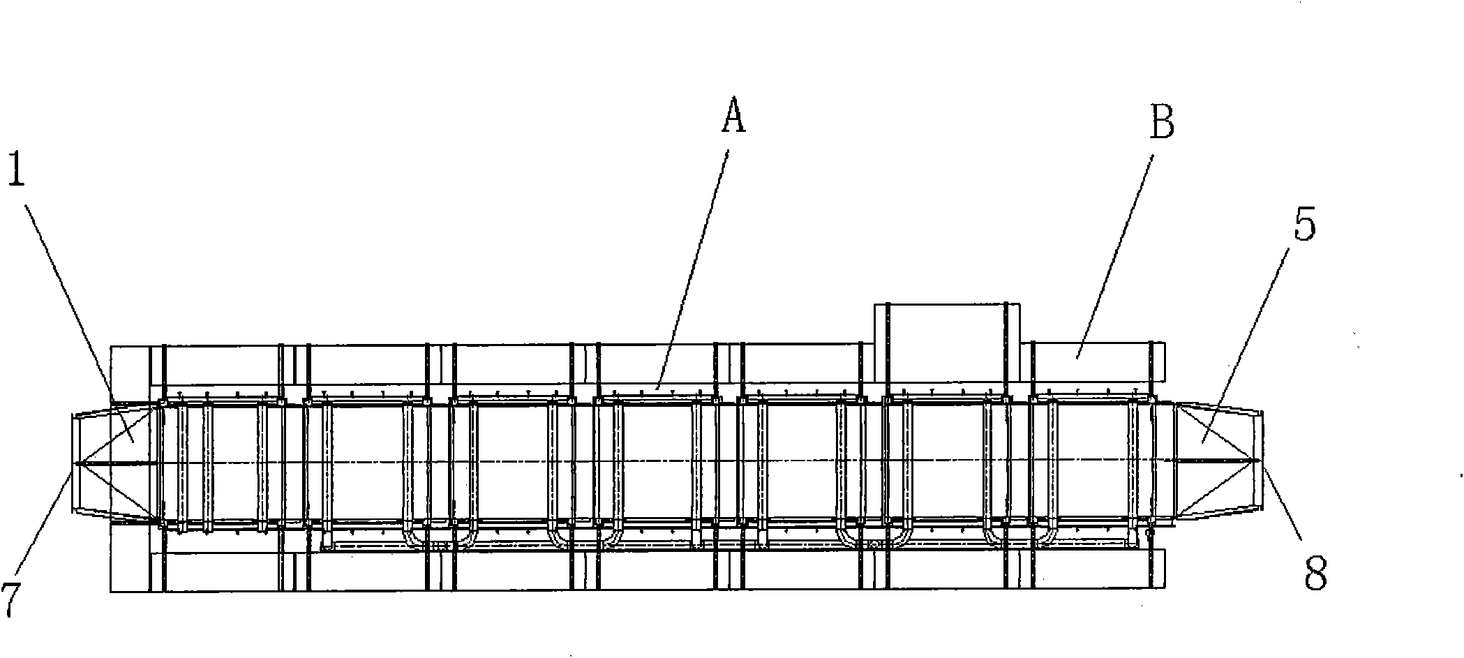
[0039] like figure 1 , figure 2 and image 3As shown, the modular combined waste heat boiler of the present invention is provided with a flue gas inlet smoke box 1, a superheater module group 2, an evaporator module group 3, a preheater module group 4 and a flue gas outlet smoke box 5 in sequence from left to right In addition, a steam drum assembly 6 is arranged on the upper part of the superheater module group, the evaporator module group and the preheater module group to form a modular waste heat boiler of the present invention.

[0040] The module type and the way of assembling in embodiment 1 are as follows figure 1 As shown, it is specifically a flue gas inlet smoke box 1, the number of superheaters in the superheater module group 2 is 2, the number of evaporators in the evaporator module group 3 is 3, and the number of preheaters in the preheater module group 4 The number of heaters is 2, plus a flue gas outlet smoke box 5, and a steam drum assembly 6 connected to i...

Embodiment 2

[0042] specific structure reference figure 1 , figure 2 and image 3 , the difference lies in the number of components in each module group, specifically: the number of superheaters in superheater module group 2 is 1, the number of evaporators in evaporator module group 3 is 2, and the number of evaporators in preheater module group 4 The number of preheaters is 1. In addition, because the number of components is small, a smaller steam drum assembly can be used. The installation settings of the remaining flue gas inlet smoke box 1 and flue gas outlet smoke box 5 are the same as in Example 1. , the installation method of the modular waste heat boiler in this embodiment is the same as that in Embodiment 1, but due to the small number of components, the floor area is small, and it is suitable for the waste heat utilization field of small boilers.

Embodiment 3

[0044] specific structure reference figure 1 , figure 2 and image 3 , the difference lies in the number of components in each module group, specifically: the number of superheaters in superheater module group 2 is 3, the number of evaporators in evaporator module group 3 is 6, and the number of preheater module group 4 The number of preheaters is 3. In addition, due to the large number of components, a larger steam drum assembly is required. The installation settings of the remaining flue gas inlet smoke box 1 and flue gas outlet smoke box 5 are the same as in Example 1. The installation method of the modular combined waste heat boiler of this embodiment is the same as that of Embodiment 1, but due to the large number of components, it occupies a larger area, but it is still smaller than the integrated waste heat boiler in the prior art, and is suitable for large boilers waste heat utilization field.

[0045] In order to simplify the installation of the modular combined w...


PUM


Abstract

The invention provides a module combined type exhaust-heat boiler which comprises an exhaust-heat boiler assembly and an exhaust-heat boiler terrace, wherein the exhaust-heat boiler assembly is arranged on the exhaust-heat boiler terrace; the exhaust-heat boiler assembly comprises a fume inlet smoke box, a superheater module group, an evaporator module group, a preheater module group and a fume outlet smoke box which are successively connected from left to right; a steam pocket assembly is arranged above the superheater module group, the evaporator module group and the preheater module group; and the total exhaust-heat boiler assembly is horizontal. The key component part of the module combined type exhaust-heat boiler is in a module combined type design; the specific number of the assemblies can be conveniently regulated when in installation, correspondingly components just need to be installed or disconnected when the number of the assemblies needs to be additionally added or reduced, and the whole exhaust-heat boiler dose not need to be disassembled, thereby greatly reducing the period of construction, reducing the field installation and check workloads of various components of the exhaust-heat boiler and ensuring the whole quality of the exhaust-heat boiler.

Description

technical field [0001] The invention relates to a boiler, in particular to a waste heat boiler used to convert waste heat generated in industrial production into other energy sources. Background technique [0002] Boilers that use the sensible heat of various waste gases and waste heat after waste incineration as heat sources are called waste heat boilers, also known as waste heat boilers. Some waste heat boilers only produce hot water or steam, and some can also produce steam to drive a steam turbine to generate electricity. As far as the circulation mode is concerned, there are two types of waste heat boilers: natural circulation and control circulation. From the arrangement of the heating surface, there are vertical and horizontal arrangements. [0003] And the industrial boiler under the present prior art, its essence is a kind of industrial electric furnace system that consumes huge power. It mainly consists of furnace shell, furnace cover, furnace lining, short net,...

Claims


Application Information

Patent Timeline
Patent Type & Authority Applications(China)
IPC IPC(8): F22B1/18
Inventor 李俊倪中
Owner SHANGHAI NENGCHUANG SCI TECH
Why Eureka
Try Eureka