Heat exchange tube internal radial direction ladder-type rotor

A stepped heat exchange tube technology, which is applied in heat transfer modification, heat exchange equipment, lighting and heating equipment, etc., can solve the problem that the damage effect of the boundary layer of the heat transfer fluid is not obvious, reduce the friction between the shaft and the bearing seat, Problems such as high pressure of heat exchange tubes can achieve the effect of saving materials, improving the degree of damage, and preventing the deposition of dirt

Inactive Publication Date: 2011-06-01
SINO ECO TECH
View PDF2 Cites 12 Cited by
  • Summary
  • Abstract
  • Description
  • Claims
  • Application Information

AI Technical Summary

Problems solved by technology

In recent years, there have been many methods and devices to prevent fouling deposition. The patent application number is 00249059.5 "A Heat Transfer Tube Equipped with Scale Removal and Anti-Scale Devices". To achieve enhanced heat transfer, the specific method is to put a movable ball on one section of the shaft and connect it with the bearing seat, and connect the other end of the shaft with a spiral bond. This method reduces the friction between the shaft and the bearing seat. The normal rotation of the spiral bond is guaranteed, but the position of the spiral bond in the tube is not well restricted, and it may be rubbed against the tube wall by the action of the fluid, resulting in wear of the heat exchange tube, and because the spiral bond is a whole, The heat transfer fluid in the tube needs a large driving torque when driving the link to rotate, resulting in a large pressure drop at both ends of the heat exchange tube
Chinese Patent No. ZL200520127121.9, "Rotor Type Self-cleaning Enhanced Heat Transfer Device", introduces an enhanced heat transfer device consisting of a fixed frame, rotor, steel wire and support tube. Scale and enhanced heat transfer function, the heat transfer fluid in the case of downstream or reverse flow in the heat exchange tube, all have the role of anti-scaling and enhanced heat transfer, the rotor involved in this patent when a certain heat transfer fluid passes through , the rotation speed of the rotor is determined by the helix angle of the flight. When the lead of the flight is small, the rotation speed of the rotor is faster, and at the same time, the resistance to the heat transfer fluid increases, and the heat transfer fluid is disturbed during the rotation of the rotor. effect, but the damage to the boundary layer of the heat transfer fluid near the inner wall of the heat exchange tube is not obvious

Method used


Image

  • Heat exchange tube internal radial direction ladder-type rotor
  • Heat exchange tube internal radial direction ladder-type rotor
  • Heat exchange tube internal radial direction ladder-type rotor

Examples


Embodiment Construction

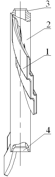
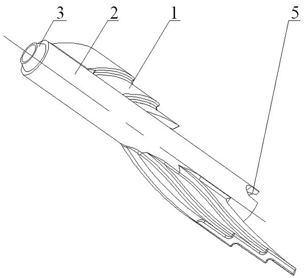
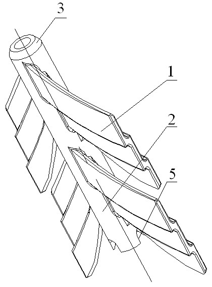
[0023] Such as Figure 5 Shown is an implementation method of the present invention involving a radially stepped rotor in a heat exchange tube. The heat transfer enhancement device includes a rotor, a pendant 6, a heat exchange tube 7 and a rotating shaft 8. Several rotors are connected in series through the rotating shaft 8. Adjacent rotors are connected by a coaxial structure 9, the pendant 6 is fixed at both ends of the heat exchange tube 7, and the two ends of the rotating shaft 8 are respectively connected with the pendant 6 to achieve both ends of the fixing, and the rotor is fixed on the hollow shaft by a certain number of stepped blades 1 2, the hollow shaft 2 also has a ball socket boss 3, a ball socket concave table 4 and a hole 5 communicating with the hollow shaft inner hole. In this example, the coaxial structure 9 is composed of the ball socket boss 3 and the ball socket concave table 4 at both ends of the rotor hollow shaft 2. Among the two adjacent rotors, the ...


PUM


Abstract

The invention relates to a heat exchange tube internal radial direction ladder-type rotor, comprising a hollow shaft and ladder-type blades, wherein the ladder-type blades are arranged on the surface of the hollow shaft. The heat exchange tube internal radial direction ladder-type rotor is characterized in that: the outer diameter of each ladder-type blade is less than the inner diameter of a heat exchange tube; the surface of the ladder-type blade is smooth; the ladder-type blades are arranged around the hollow shaft and are in spiral shapes; the ladder surface structure or a wave-type structure is arranged on both the upstream face and the downstream face of the ladder-type blade along the radial direction of the hollow shaft; and the edge of the ladder-type blade firstly touching the water flow presents an inverted oblique angle or an inverted round angle. In the invention, axial force is generated to the ladder-type rotor when heat transfer fluid in the heat exchange tube flows and the flow of the fluid is hindered by the blade, therefore the flow direction of the fluid is changed and mixed flow is formed; in the meantime, the rotor is driven by the fluid to turn; the mixed flow of the heat transfer fluid is strengthened; part heat transfer fluid flows along the ladder surface of each blade and finally leaves the ladder surface to do eccentric exercise and is thrown to the inner wall surface of the heat exchange tube; thereby the fluid boundary layer at the inner wall surface is impacted and further the heat transfer is strengthened.

Description

technical field [0001] The invention relates to an interpolation element used in shell-and-tube heat exchangers, heat exchange reactors, etc. As the power, the radial stepped rotor realizes self-cleaning and enhanced heat transfer function. Background technique [0002] In the 21st century, energy conservation and emission reduction has become the consensus of human beings in the process of social development. As a general-purpose equipment widely used in chemical industry, oil refining, power, food, light industry, atomic energy, pharmaceuticals, machinery and many other industrial sectors, heat exchangers are particularly concerned about their energy consumption. As the most widely used heat exchanger, the shell-and-tube heat exchanger has the disadvantage that it is easy to deposit dirt inside. These dirt will increase the transmission resistance of the heat transfer fluid in the pipeline, and even block the pipeline in severe cases, caused by dirt. The thermal resistan...

Claims


Application Information

Patent Timeline
Patent Type & Authority Applications(China)
IPC IPC(8): F28F13/02F28F13/12F28F19/00
Inventor 杨卫民赵本华彭威阎华刘泽
Owner SINO ECO TECH
Why Eureka
Try Eureka