Method and apparatus for controlling the size of a laser beam focal spot

A technology of laser beam and focal spot, applied in the field of size control, can solve problems such as large distances

Active Publication Date: 2011-06-01
盈天实业(深圳)有限公司
View PDF2 Cites 50 Cited by
  • Summary
  • Abstract
  • Description
  • Claims
  • Application Information

AI Technical Summary

Problems solved by technology

[0006] The methods discussed above for line width control (where the focal point is moved relative to the substrate surface) are simple and effective, but have the following problem: During laser processing, it is often necessary to keep the substrate at the exact focal point of the beam
However, unless the distance from the telescope to the lens is very large, there are some problems with this method

Method used


Image

  • Method and apparatus for controlling the size of a laser beam focal spot
  • Method and apparatus for controlling the size of a laser beam focal spot
  • Method and apparatus for controlling the size of a laser beam focal spot

Examples


Embodiment Construction
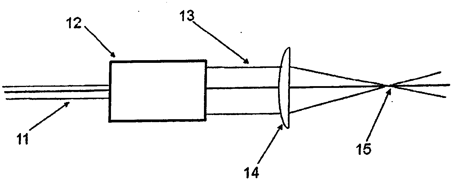
[0041] figure 1

[0042] figure 1 A standard method of conditioning a laser beam for direct write laser processing is shown. An input laser beam 11 generally having a smaller diameter passes through a transmission beam expander telescope 12 and becomes an output beam 13 with a larger diameter. The lens 14 then focuses the beam 13 into a small focal spot 15 whose diameter and distance from the lens 14 depends on the diameter and collimation of the laser beam 13 .
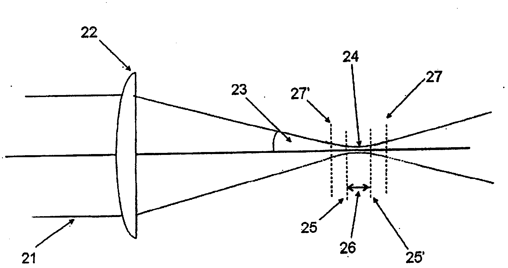
[0043] figure 2

[0044] figure 2 Details of the laser beam near the focal spot are shown. The beam 21 is focused by a lens 22 such that the beam converges at a half angle 23 to a beam waist or focal point 24 before expansion. For the case where the beam entering the focusing lens 22 is collimated, the smallest diameter (d) of the beam in the waist region 24 is a function of the following parameters: laser wavelength (λ); quality of the laser beam relative to a fully diffraction-limited beam (M2); the d...


PUM


Abstract

A method and apparatus is described that allows the width of fine line structures ablated or cured by a focussed laser beam on the surface of flat substrates to be dynamically changed while the beam is in motion over the substrate surface while simultaneously maintaining the beam focal point accurately on the surface. A three-component variable optical telescope is used to independently control the beam diameter and collimation by movement of first and second optical components relative to the third optical component. The method allows different focal spot diameters and different ablated or cured line widths to be rapidly selected and ensures that the beam shape in the focal spot remains constant and the depth of focus is always maximized.

Description

technical field [0001] The invention relates to the control of the size of the focal spot of a laser beam formed on a substrate, for example for ablation or laser curing of materials by direct writing. The invention is particularly suitable for high resolution, fine line patterning of thin films or layers of material on thin glass, polymer, metal or other substrates with varying thickness or unevenness. Background technique [0002] The use of lasers to ablate or solidify fine line structures in or on the surface of flat substrates is well known, and many different devices are used to accomplish these operations. The common features of the equipment used are: a laser system that emits a pulsed beam or a continuous beam, a focusing lens that focuses the laser beam into a spot on the substrate surface, and a method of moving the laser focal spot on the substrate surface. [0003] The width of the ablated or solidified line structures in the surface of the material on the subs...

Claims


Application Information

Patent Timeline
Patent Type & Authority Applications(China)
IPC IPC(8): G02B27/09B23K26/00
CPCB23K26/0807B23K26/0665B23K26/046B23K26/367B23K26/0648G02B27/09G02B27/0938B23K26/082B23K26/364B23K26/06
Inventor D·C·米尔恩
Owner 盈天实业(深圳)有限公司
Why Eureka
Try Eureka