Fpc connector for electrically connecting fpc to pcb and fpc connection method using the same
A connector and electrical connection technology, applied in the direction of connection, fixed connection, circuit, etc., can solve the problems of increased defect rate, etc., and achieve the effect of easy and simple assembly, noise-free connection, and good connection
- Summary
- Abstract
- Description
- Claims
- Application Information
AI Technical Summary
Problems solved by technology
Method used
Image

Examples
no. 1 example
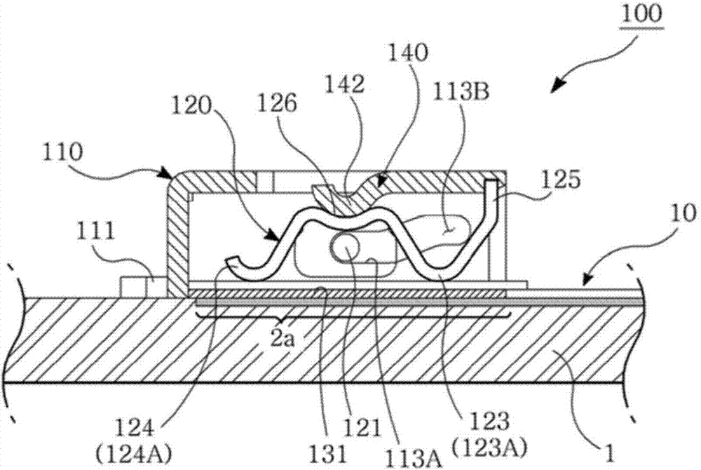
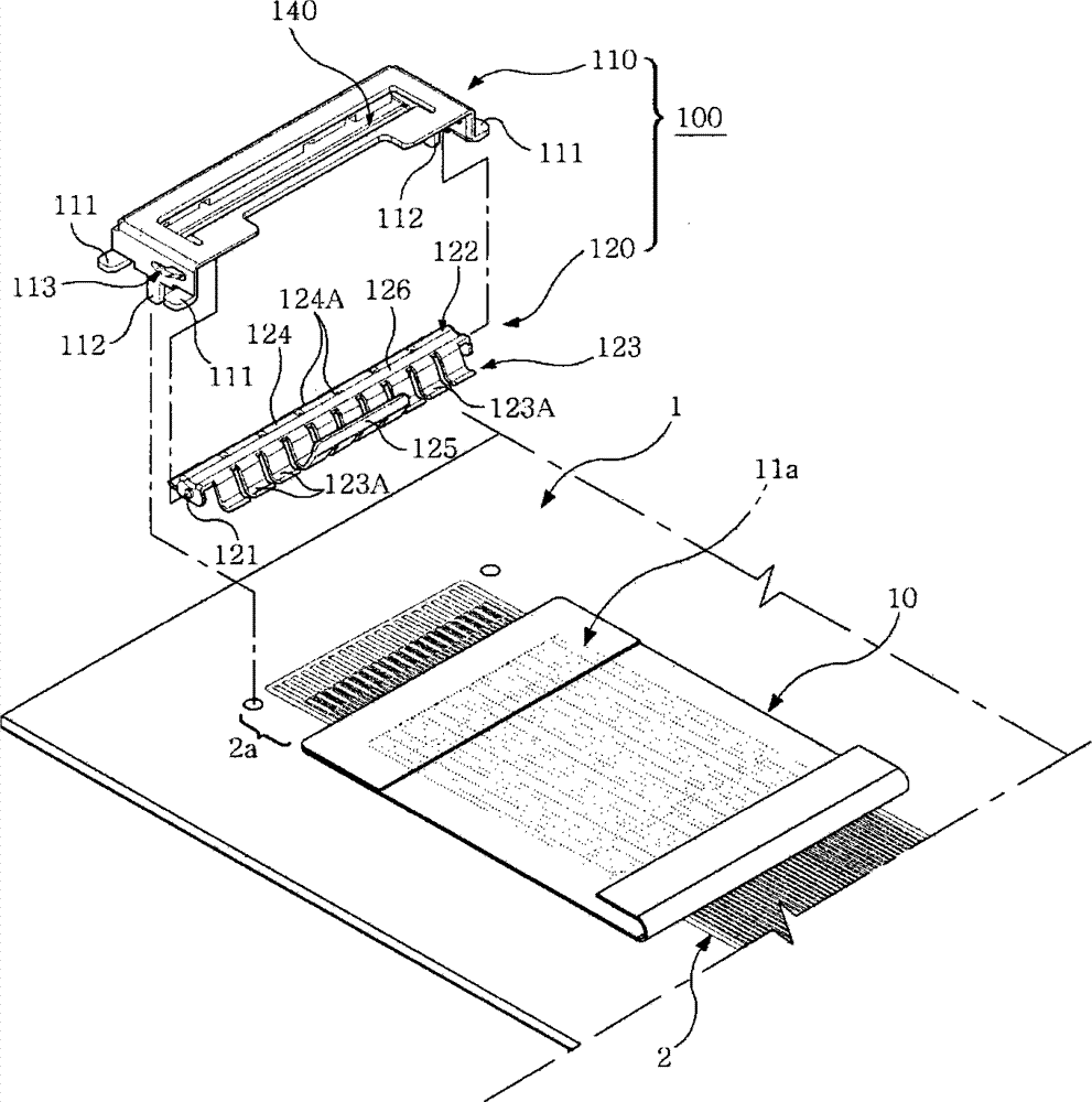
[0032] Figure 1 to Figure 3 A first embodiment of the present invention is shown.
[0033] The FPC connector 100 according to the first embodiment relates to a “Board-to-FPC” connector, which electrically connects the flat wire 11 of the FPC 10 with the flat wire 2 on the PCB 1 .
[0034] The PCB 1 has a flat wire 2 printed on its surface, and the flat wire 2 has a contact portion 2a at the end. The contact portion 2 a of the PCB 1 is in direct contact with the contact portion 11 a of the FPC 10 .
[0035] The FPC connector 100 according to the first embodiment of the present invention includes: a housing 110 fixed on the PCB1; and a pressurizing part 120, the pressurizing part 120 causes the FPC10 inserted in the housing 110 to press the PCB1 so that the FPC10 contacts the PCB1 .
[0036] The housing 110 includes a plurality of fixing parts 111 and a plurality of mounting legs 112 on the sidewall, and the housing 110 is fixed on the PCB 1 by using the fixing parts 111 and...
no. 2 example
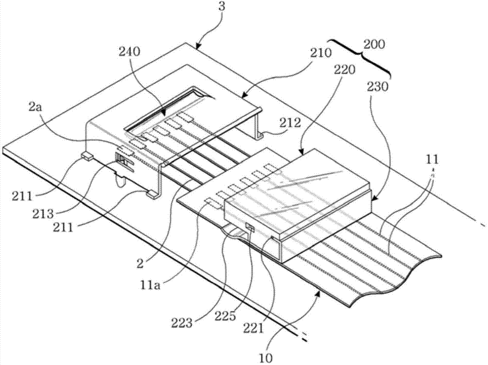
[0058] Figure 4 to Figure 7 An FPC connector according to a second embodiment of the present invention is shown.
[0059] Such as Figure 4 As shown, the FPC connector 200 according to the second embodiment includes: a housing 210, which is fixed on the PCB1; a pressing member 220, which makes the contact portion 11a of the FPC10 in the housing 210 press the PCB1 so that the contact portion of the FPC10 11a contacts the contact portion 2a of the cable 2 on the PCB1.
[0060] The housing 210 includes a plurality of fixing parts 211 on the sidewall, and the housing 210 is fixed on the PCB 1 through the fixing parts 211 . The fixing part 211 is fixed on the PCB by soldering.
[0061] The housing 210 is fixedly installed on the PCB 1 to cover the cable contact portion 2 a on the PCB 1 . The housing 210 is open at the bottom to allow the cable contact portion 2a to be disposed therein.
[0062] The housing 210 includes a biasing element 240 for pressurizing the pressing membe...
no. 3 example
[0066] Figure 8 and Figure 9 An FPC connector according to a third embodiment of the present invention is shown.
[0067] Such as Figure 8 and Figure 9 As shown, the FPC connector 300 according to the third embodiment includes: a housing 310, which is fixed on the PCB1; a pressurizing part 320, which makes the contact portion 11a of the FPC10 in the housing 310 press the PCB1, so that the FPC10 The contact portion 11 a contacts the contact portion 2 a of the cable 2 on the PCB 1 .
[0068] The housing 310 includes a plurality of fixing parts 311 on the sidewall, and the housing 310 is fixed on the PCB 1 through the fixing parts 311 . The fixing part 311 is fixed on the PCB by soldering.
[0069] The pressing member 320 includes: a sleeve portion 321 rotatably supporting the shaft member 331 ; a finer plate 322 extending from the sleeve portion 321 ; and a pressing plate 323 for pressing the FPC 1 . The housing 310 also includes stops 310C, 310D for keeping the compre...
PUM
 Abstract
Description
Claims
Application Information
 - R&D Engineer
- R&D Manager
- IP Professional
- Industry Leading Data Capabilities
- Powerful AI technology
- Patent DNA Extraction
Browse by: Latest US Patents, China's latest patents, Technical Efficacy Thesaurus, Application Domain, Technology Topic.
© 2024 PatSnap. All rights reserved.Legal|Privacy policy|Modern Slavery Act Transparency Statement|Sitemap