Navigation equipment for femoral medullary cavity cutting operation by femoral myelocavity file

A technology of navigation equipment and intramedullary rasp, which is used in surgical navigation systems, operations, applications, etc., can solve the problem of reducing the degree of matching between the proximal femoral medullary cavity and the hip joint femoral stem prosthesis, the inability of the femoral stem prosthesis to be implanted in place, Increase the operation time and other problems to achieve the effect of improving the success rate of one implantation

Inactive Publication Date: 2013-05-08
JIANGSU UNIV
View PDF0 Cites 0 Cited by
  • Summary
  • Abstract
  • Description
  • Claims
  • Application Information

AI Technical Summary

Problems solved by technology

In some hip replacement operations, due to the deviation between the centerline of the medullary cavity file cutting guide and the centerline of the patient's femoral cavity, the femoral stem prosthesis cannot be implanted in place, and even the patient's femur fractures
When the prosthesis cannot be implanted in place, it is usually necessary to take X-rays of the surgical site to determine the stuckness of the femoral stem prosthesis, which not only greatly increases the operation time, but also exposes the patient to the radiation damage of X-rays again
Then take out the stuck femoral stem prosthesis, and then according to the stuck femoral stem prosthesis, file off the cancellous bone of the patient's proximal femur to facilitate the implantation of the femoral stem prosthesis, which will greatly reduce the distance between the proximal femoral medullary cavity and the femoral stem prosthesis. The degree of matching between the femoral stem prosthesis of the hip joint increases the risk of early loosening of the femoral stem prosthesis, which is not conducive to the postoperative rehabilitation of patients

Method used


Image

  • Navigation equipment for femoral medullary cavity cutting operation by femoral myelocavity file
  • Navigation equipment for femoral medullary cavity cutting operation by femoral myelocavity file
  • Navigation equipment for femoral medullary cavity cutting operation by femoral myelocavity file

Examples


Embodiment Construction

[0018] The present invention will be further described below in conjunction with the accompanying drawings:

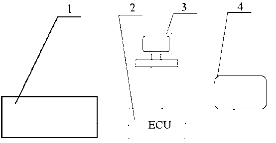
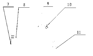
[0019] A schematic diagram of a navigation device for rasp cutting the femoral cavity operation is as follows figure 1 As shown, it mainly includes: acquisition unit 1, central control unit 2, display unit 3, button keyboard 4; acquisition unit 1 for sampling point position information is connected with central control unit 2, and central control unit 2 is used for displaying guide The display unit 3 is respectively connected with the button keyboard 4 for control, and the central control unit 2 controls the acquisition unit 1 to sample the position information of the points and calculates the cutting guide. Acquisition unit 1 consists of a robotic arm, such as figure 2 As shown, it is mainly composed of a contact 7 , a contact base 8 , two sections of lever arms 9 , an angle sensor 10 and a base 11 , wherein the contact 7 is a sphere and is fixed on the contact base...


PUM


Abstract

The invention relates to navigation equipment for a femoral medullary cavity cutting operation by a femoral myelocavity file, comprising an acquisition unit (1), a central control unit (2), a display unit (3), a button keyboard (4), a positioning board (5) and a probe (6), wherein the central control unit (2) is respectively connected with the acquisition unit (3), the display unit (3) and the button keyboard (4); the central control unit (2) controls the acquisition unit (1) to sample point position information and work out a cutting guide passage; three sampling points (501, 502, 503) are arranged on the positioning board (5) and form three vertices of a right triangle; two sampling points (1201, 1202) are arranged on the center line of the back end (12) of the probe (6); and two sampling points (1501, 1502) are arranged on the center line of a guide rod (15) of a driver-extractor of the femoral myelocavity file. The equipment can determine the relative position relation between thecenter line of a femoral medullary cavity and the center line of a femoral myelocavity file cutting guide passage, thereby improving the success rate in implantation of femoral stem prosthesis once.

Description

technical field [0001] The invention relates to a medical navigation device, in particular to a navigation device used for cutting the femoral cavity with the intramedullary rasp during hip joint replacement surgery. Background technique [0002] In the process of human hip replacement surgery, it is necessary to use the intramedullary reamer to remove part of the cancellous bone at the base of the proximal femoral neck to facilitate the implantation of the hip femoral stem prosthesis. In a hip replacement surgery using a customized femoral stem prosthesis, the hip femoral stem prosthesis is required to match the patient's femoral cavity as closely as possible. Therefore, when a customized femoral stem prosthesis is processed, it will be simultaneously A corresponding intramedullary rasp is customized for cutting the proximal femoral cancellous bone. The matching area of ​​this intramedullary rasp is slightly smaller than the corresponding matching area of ​​the femoral stem...

Claims


Application Information

Patent Timeline
Patent Type & Authority Patents(China)
IPC IPC(8): A61B19/00A61B17/56A61B34/20
Inventor 马如宇王杰张永康
Owner JIANGSU UNIV
Why Eureka
Try Eureka