Integral-assembling type heat-insulating oil pipe connection structure

A technology for insulating oil pipes and connecting structures, which is applied in the direction of protecting pipes, casings, and threaded connections through heat insulation, which can solve problems such as corrosion, reduce heat loss, solve joint thread leakage, and improve heat insulation conditions.

Active Publication Date: 2011-06-08
JIANGSU CHANGBAO STEELTUBE CO LTD
View PDF8 Cites 9 Cited by
  • Summary
  • Abstract
  • Description
  • Claims
  • Application Information

AI Technical Summary

Problems solved by technology

[0006] For the above purpose, the applicant disclosed a joint connection structure of heat-insulated oil pipe in application number 201010513674.3, which can not only reduce the heat loss at

Method used


Image

  • Integral-assembling type heat-insulating oil pipe connection structure
  • Integral-assembling type heat-insulating oil pipe connection structure
  • Integral-assembling type heat-insulating oil pipe connection structure

Examples


Embodiment 1

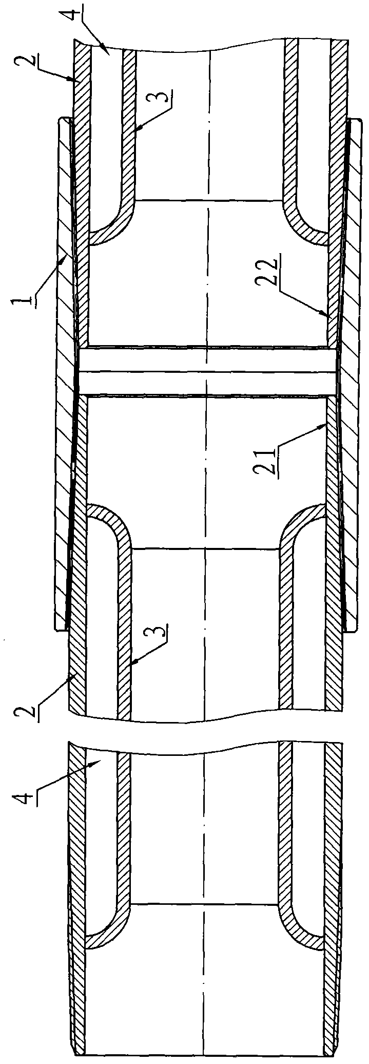
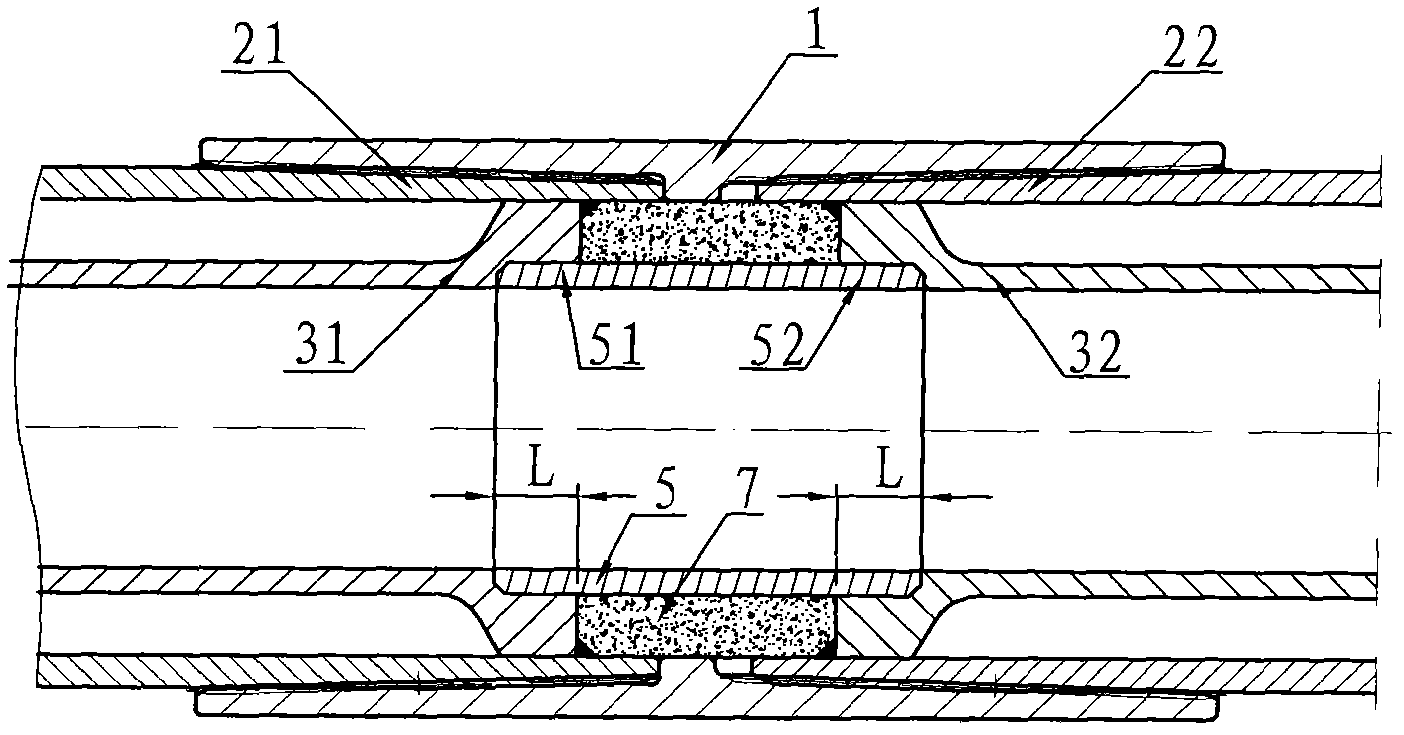
[0033]Embodiment 1: The connection structure of the overall jacketed heat-insulated oil pipe, such as image 3 As shown, it includes the coupling 1, the factory end 21 of the outer pipe threaded with the left end of the coupling 1, the user end 22 of the outer pipe threaded with the right end of the coupling 1, and the factory end 21 of the outer pipe is welded sealingly with the inner pipe factory End 31, in the outer pipe user end 22, is welded with the pipe user end 32 in the pipe body sealingly, is provided with the pipe end inner pipe 5 between the pipe factory end 31 in the pipe body and the pipe user end 32 in the pipe body, and the pipe factory end in the pipe body 31 and the pipe user end 32 in the pipe body are all provided with a butt joint, the axial length of the butt joint is L, and the inner pipe 5 factory end 51 of the pipe end is press-fitted on the butt joint of the pipe factory end 31 in the pipe body with an interference fit. In the mouth, the matching leng...

Embodiment 2

[0034] Embodiment 2: The connection structure of the overall set type heat insulation oil pipe, such as Figure 4 ~ Figure 8 As shown, it includes the coupling 1, the factory end 21 of the outer pipe threaded with the left end of the coupling 1, the user end 22 of the outer pipe threaded with the right end of the coupling 1, and the factory end 21 of the outer pipe is welded sealingly with the inner pipe factory End 31, in the outer pipe user end 22, is welded with the pipe user end 32 in the pipe body sealingly, is provided with the pipe end inner pipe 5 between the pipe factory end 31 in the pipe body and the pipe user end 32 in the pipe body, and the pipe factory end in the pipe body 31 and the pipe user end 32 in the pipe body are provided with a butt joint, the axial length of the butt joint is L, and the inner pipe factory end 51 of the pipe end is press-fitted in the butt joint of the pipe factory end 31 in the pipe body by interference fit , the matching length L betwe...


PUM

PropertyMeasurementUnit
Axial lengthaaaaaaaaaa

Abstract

The invention discloses an integral-assembling type heat-insulating oil pipe connection structure which comprises a box coupling, a factory end of an outer pipe, and a user end of the outer pipe, wherein the insides of the factory end and user end of the outer pipe are respectively hermetically welded with a pipe-body inner pipe, and a pipe-end inner pipe is arranged between a factory end of the pipe-body inner pipe and a user end of the pipe-body inner pipe, the two ends of the pipe-end inner pipe are connected with the factory end and user end of the pipe-body inner pipe by a seal butt joint structure, and a closed pipe-end heat-insulating cavity is formed between the pipe-end inner pipe and the factory end of the pipe-body inner pipe as well as the factory end of the outer pipe, the box coupling, the user end of the pipe-body inner pipe and the user end of the outer pipe; the inside of the pipe-end heat-insulating cavity is provided with a heat-insulating sleeve; and a seal structure is formed between the factory end of the pipe-body inner pipe and the pipe-end inner pipe as well as the user end of the pipe-body inner pipe, and can reduce the heat conduction, heat convection and radiation effects of the connecting part of the box coupling, thereby reducing the heat loss of the connecting part of the box coupling and improving the sealing performance of the connecting part of the box coupling, and the seal structure can prevent the occurrence of a problem that the box coupling is easy to corrode at high temperature.

Description

【Technical field】 [0001] The invention relates to a connection structure of heat-insulated oil pipe joints for thermal recovery of heavy oil, in particular to a connection structure of vacuum heat-insulated oil pipe joints. 【Background technique】 [0002] Crude oil with high viscosity and high specific gravity is called heavy oil. The viscosity of heavy oil changes significantly with temperature. Tests show that for heavy oil, if the temperature increases by 8-9 °C, its viscosity can be reduced by half. Therefore, for the exploitation and transportation of heavy oil, heat is often used to reduce its viscosity; injecting steam into the underground heavy oil layer is the main technical measure for heavy oil exploitation in the petroleum industry, commonly known as "steam huff and puff method for thermal recovery of heavy oil" or " steam driven method". [0003] When injecting high-temperature (200°C-350°C) steam into the ground, in order to reduce the loss of heat and reduce...

Claims


Application Information

Patent Timeline
IPC IPC(8): E21B17/02E21B43/24F16L59/18F16L15/04
Inventor 周家华
Owner JIANGSU CHANGBAO STEELTUBE CO LTD
Why Eureka
Try Eureka