Speed increasing box for compressor

A speed-increasing gearbox and compressor technology, which is applied in the direction of mechanical equipment, bearings, rotating bearings, etc., can solve shock wave stall and chattering, occupy a large area, and the speed-up ratio cannot meet the requirements of transonic input speed, etc. problem, to achieve the effect of solving difficult processing, small energy loss and compact structure

Inactive Publication Date: 2011-06-08
杭州南方通达齿轮有限公司
View PDF6 Cites 3 Cited by
  • Summary
  • Abstract
  • Description
  • Claims
  • Application Information

AI Technical Summary

Problems solved by technology

[0003] The invention provides a speed-up box for a compressor with a compact structure, a large speed-up ratio, a reasonable design, and no shock wave stall and chattering; it solves the problem that the speed-up box structure in the prior art occupies a large area , the speed-up ratio cannot meet the requirements of the transonic input speed, and the technical problems of shock stall and chattering are likely to occur

Method used


Image

  • Speed increasing box for compressor
  • Speed increasing box for compressor
  • Speed increasing box for compressor

Examples


Embodiment 1

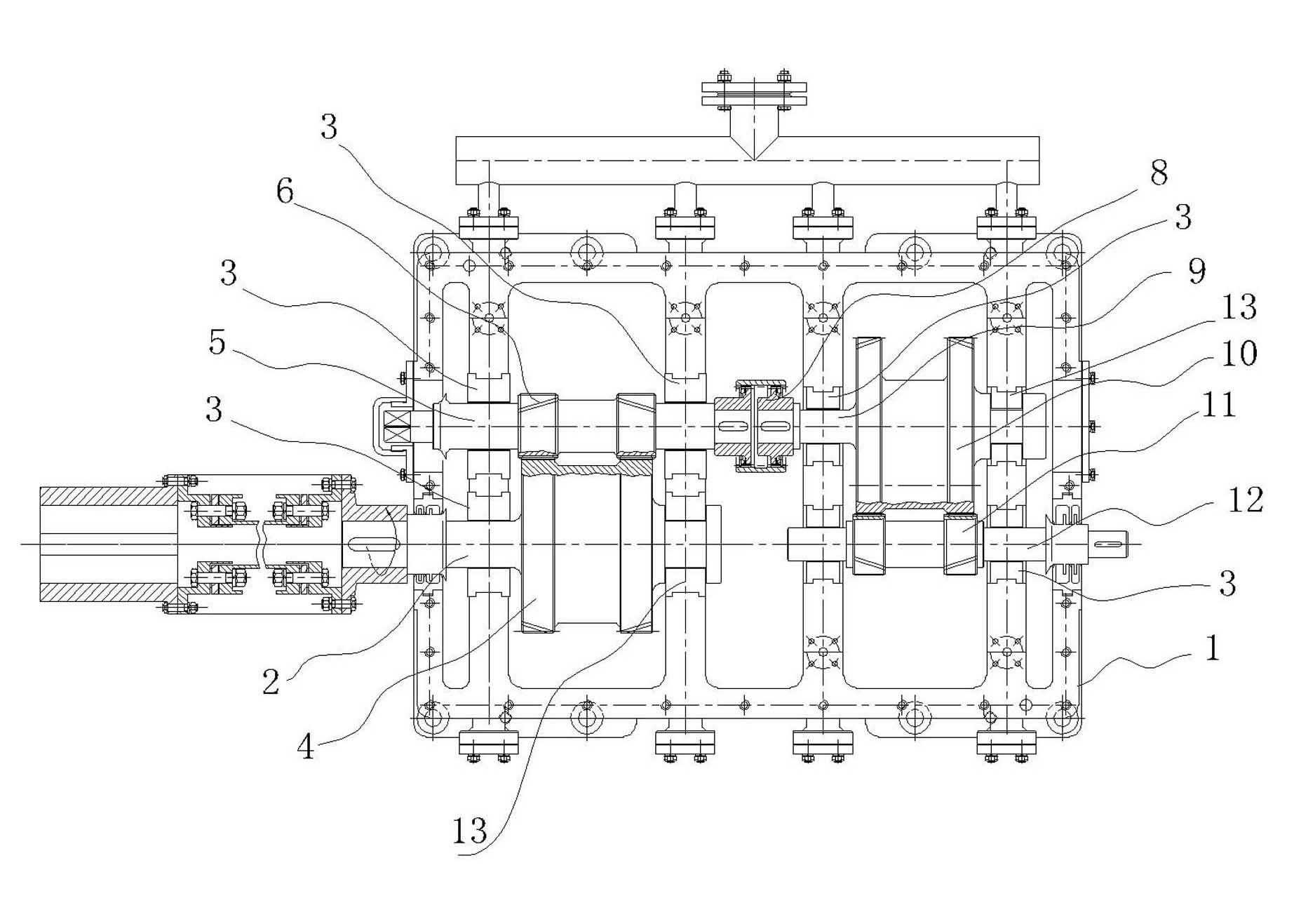
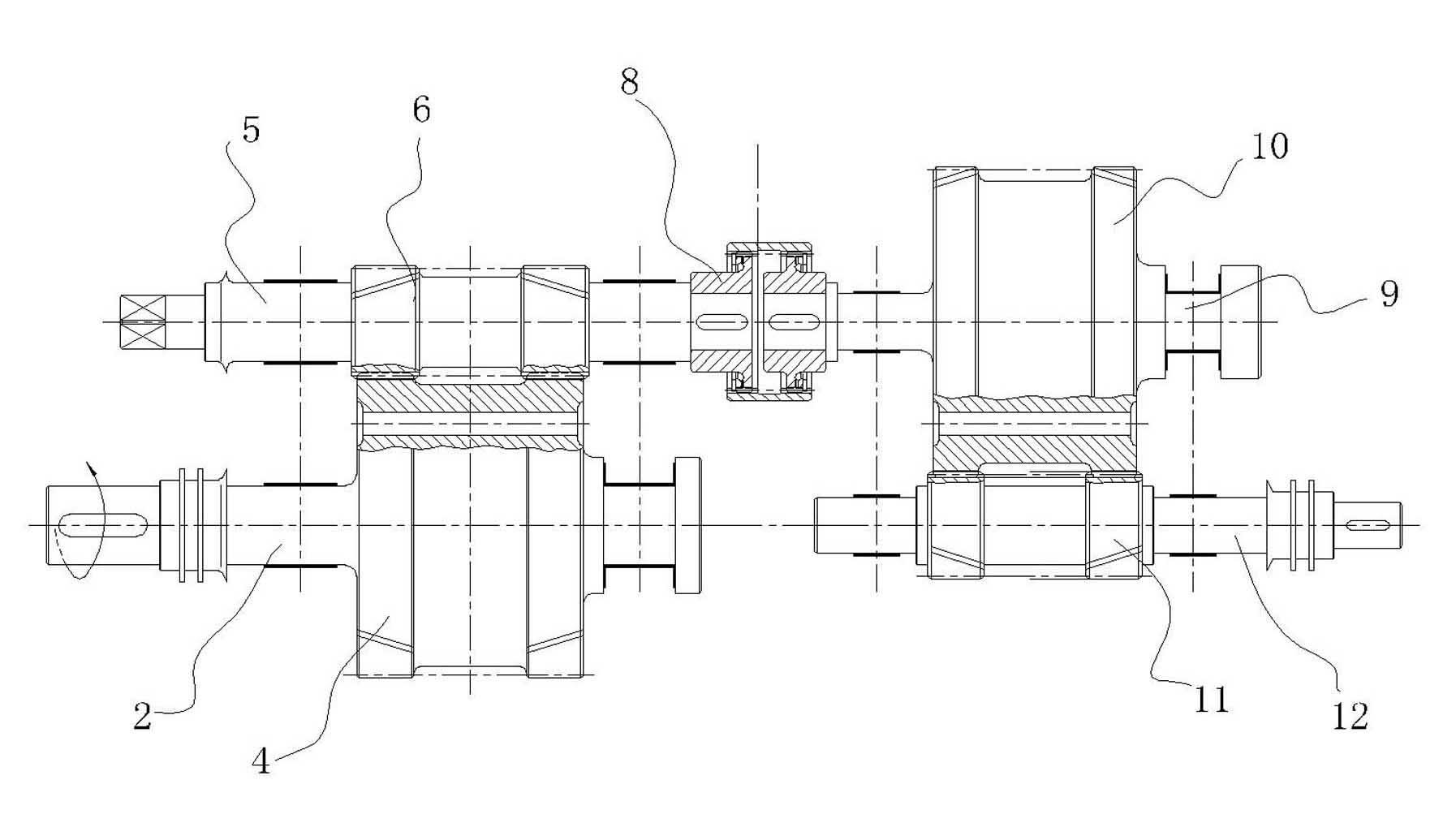
[0022] Embodiment 1: as figure 1 As shown, a speed increasing box for a compressor includes a box body 1, and a two-stage transmission mechanism is arranged in the box body 1 . One end of the first-stage input shaft wheel shaft 2 is supported by a radial bearing 3, and the other end is supported by a radial thrust bearing 13. There is a first-stage input gear 4 on the first-stage input gear shaft 2, which is driven by gear meshing transmission. The first-stage output gear shaft 5 rotates, and the first-stage output gear shaft 5 is parallel to the first-stage input gear shaft 2. There is a first-stage output pinion 6 on the first-stage output gear shaft 5, and the first-stage output gear shaft Both ends of 6 are supported by radial bearings 3, one end of the output gear shaft 5 of the first stage is designed as a manual barring structure, and the other end of the output gear shaft 5 of the first stage is connected by a gear coupling 8 with a drum tooth structure There is a se...


PUM


Abstract

The invention relates to a speed increasing box for a compressor, and the speed increasing box is applied to an experiment table of a transonic speed axial flow compressor. The speed increasing box for the compressor comprises a box body, wherein the box body is internally provided with a two-stage gear transmission structure; the two-stage gear transmission structure comprises a primary input gear shaft, a primary output gear shaft, a secondary input gear shaft, a secondary output gear shaft; the primary output gear shaft is connected with the secondary input gear shaft; the primary output gear shaft and the secondary input gear shaft are positioned on the same main shaft; and the primary input gear shaft and the secondary output gear shaft are positioned at the same side of the main shaft. The speed increasing box for the compressor provided by the invention has the advantages of compact structure, greater speed increasing ratio and reasonable design, and can not generate shock stall and buffeting; and the technical problems in the prior art that the occupation area of the speed increasing box structure is large, the speed revolving of transonic speed input can not be satisfied by the speed increasing ratio, and the shock stall and buffeting can be easily generated are solved.

Description

technical field [0001] The invention relates to a gear speed-up box structure, in particular to a speed-up box applied on a transonic axial-flow compressor test bench. Background technique [0002] As one of the important components of the combustion engine, the compressor has an important influence on the performance of the internal combustion engine. And the design level of the transonic stage of the compressor greatly affects the performance of the compressor. The so-called transonic speed is the speed close to the speed of sound, usually refers to the speed range of 0.8 to 1.2 times the speed of sound. In the transonic range, both subsonic and supersonic regions exist in the flow field. Transonic airflow may occur around compressor blades, aircraft, helicopter rotors, and propellers. It is characterized by the occurrence of shock waves downstream of the local supersonic region, and the separation of airflow due to the mutual interference between the shock waves and th...

Claims


Application Information

Patent Timeline
Patent Type & Authority Applications(China)
IPC IPC(8): F16C23/00F16H1/20
Inventor 胡洪伟胡治祥陈迅
Owner 杭州南方通达齿轮有限公司
Why Eureka
Try Eureka