Interferometric defect detection and classification

A defect and detection system technology, applied in the field of common-optical path interference, can solve expensive, unstable, complex and other problems

Inactive Publication Date: 2011-06-08
焕・J・郑
View PDF10 Cites 51 Cited by
  • Summary
  • Abstract
  • Description
  • Claims
  • Application Information

AI Technical Summary

Problems solved by technology

However, these systems are not only complex and expensive, but also have serious disadvantages: photon noise and sample pattern noise can be excessive, and they are also unstable due to the fact that the probe and reference beams use two different optical paths
Their method is not only complex and computationally intensive, but also not suitable for detection of small defects

Method used


Image

  • Interferometric defect detection and classification
  • Interferometric defect detection and classification
  • Interferometric defect detection and classification

Examples


Embodiment Construction

[0057] A detailed description of the subject matter of the invention is provided below. While several embodiments have been described, it should be understood that the inventive body of work is not limited to any one embodiment, but includes many variations, modifications and equivalents as well as combinations of features in different embodiments. Furthermore, while numerous specific details are set forth in the following description in order to provide a thorough understanding of the inventive body of work, some embodiments may be practiced without some or all of these details. Furthermore, for the purpose of clarity, certain technical material that is known in the related technical fields has not been described in detail to avoid unnecessarily obscuring the inventive working subject. The words "reticle" and "mask" are used interchangeably herein to refer to a patterned object that is used as a subject to create other patterned objects.

[0058] Light fields can be describe...


PUM


Abstract

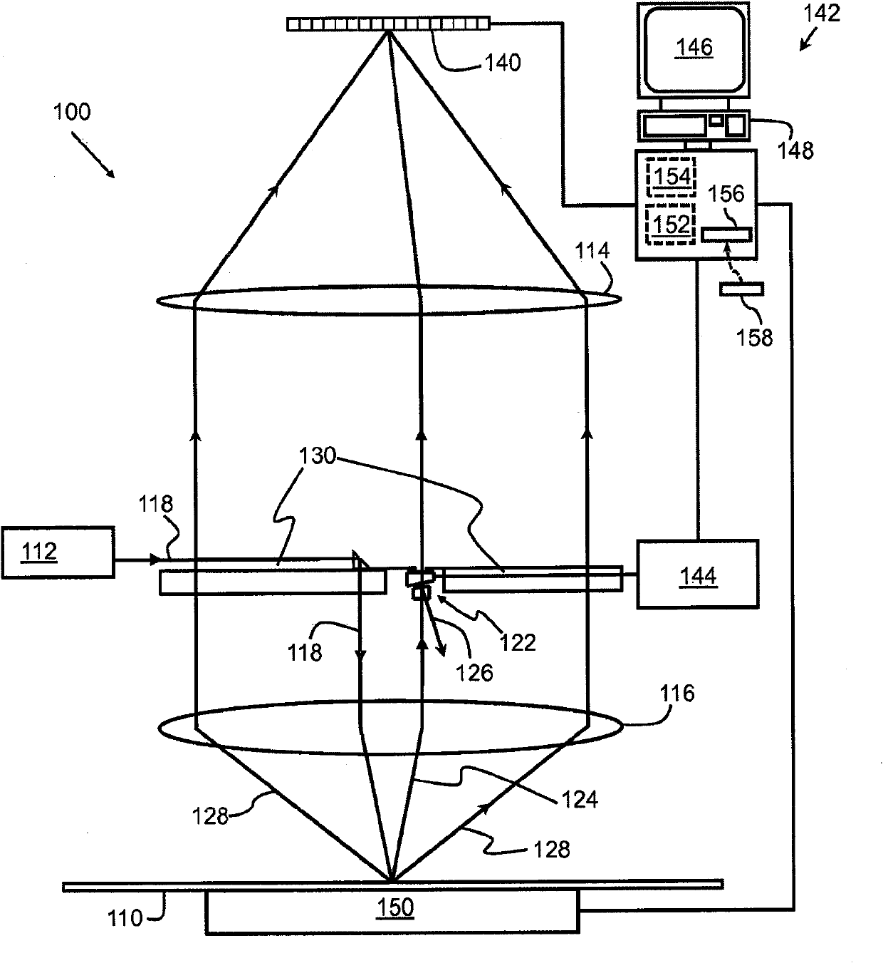
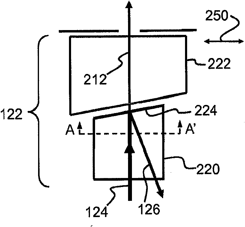
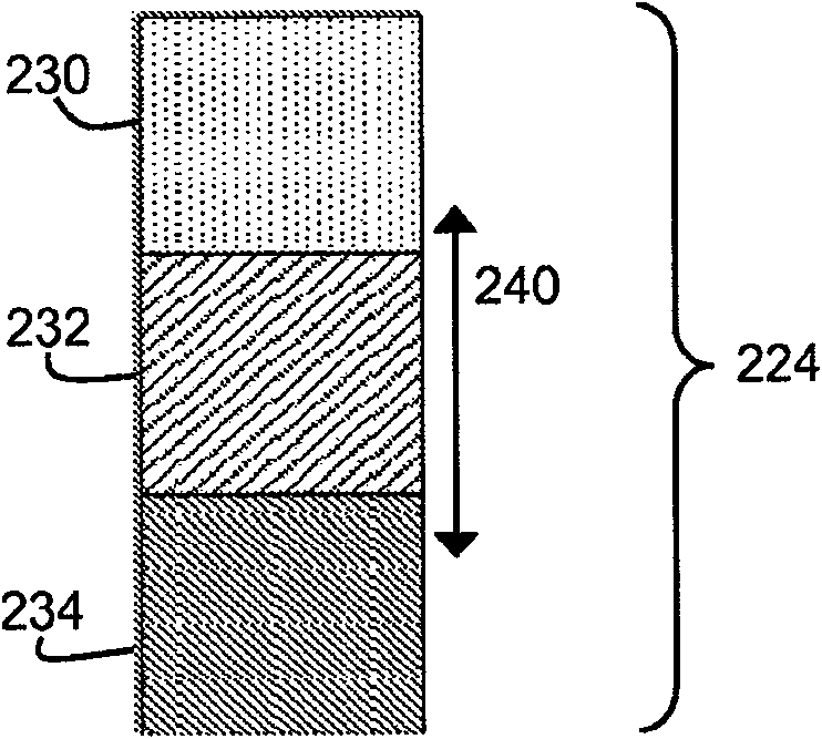
Systems and methods for using common-path interferometric imaging for defect detection and classification are described. An illumination source generates and directs coherent light toward the sample. An optical imaging system collects light reflected or transmitted from the sample including a scattered component and a specular component that is predominantly undiffracted by the sample. A variablephase controlling system is used to adjust the relative phase of the scattered component and the specular component so as to change the way they interfere at the image plane. The resultant signal is compared to a reference signal for the same location on the sample and a difference above threshold is considered to be a defect. The process is repeated multiple times each with a different relative phase shift and each defect location and the difference signals are stored in memory. This data is used to calculate an amplitude and phase for each defect.

Description

[0001] Cross-references for applications [0002] This application claims U.S. Patent Application No. 12 / 190,144, filed August 12, 2008, U.S. Provisional Patent Application No. 61 / 130,729, filed June 3, 2008, U.S. Provisional Patent Application 61 / 135,616, U.S. Provisional Patent Application 61 / 189,508, filed August 20, 2008, U.S. Provisional Patent Application 61 / 189,509, filed August 20, 2008, U.S. Provisional Patent Application 61, filed August 20, 2008 / 189,510, and U.S. Provisional Patent Application No. 61 / 210,513, filed March 19, 2009, each of which is incorporated herein by reference. technical field [0003] This patent specification relates to common-optical path interference. More specifically, this patent specification relates to high-resolution common-optical path interference imaging for detection and classification of defects in microlithographic devices, such as semiconductor devices and integrated circuits, and defects in lithographic reticles. Background ...

Claims


Application Information

Patent Timeline
Patent Type & Authority Applications(China)
IPC IPC(8): G01B9/02
CPCG01N21/45G01N21/9501
Inventor 焕・J・郑
Owner 焕・J・郑
Why Eureka
Try Eureka