

Method for distributing pressure gas in liquid and special equipment thereof
A distribution method and pressure gas technology, which is applied in the field of variable-efficiency towers, can solve the problems of decreased purification of packed towers, easy plugging of packings, aging of packings, etc., and achieve the effects of improving mass transfer speed, large absorption driving force, and fast reaction speed
Inactive Publication Date: 2011-06-15
张立强
View PDF4 Cites 0 Cited by
- Summary
- Abstract
- Description
- Claims
- Application Information
AI Technical Summary
Problems solved by technology
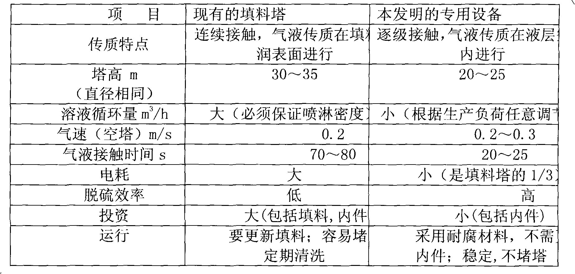
The invention mainly solves the problems of the existing wet desulfurization packed towers such as decreased purification degree, easy plugging of fillers, aging of fillers and corrosion of equipment, etc.
Method used
View moreImage
Smart ImageViewing Examples

Examples
Embodiment 1
Login to View More PUM
 Abstract
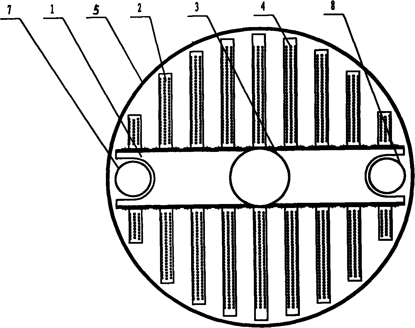
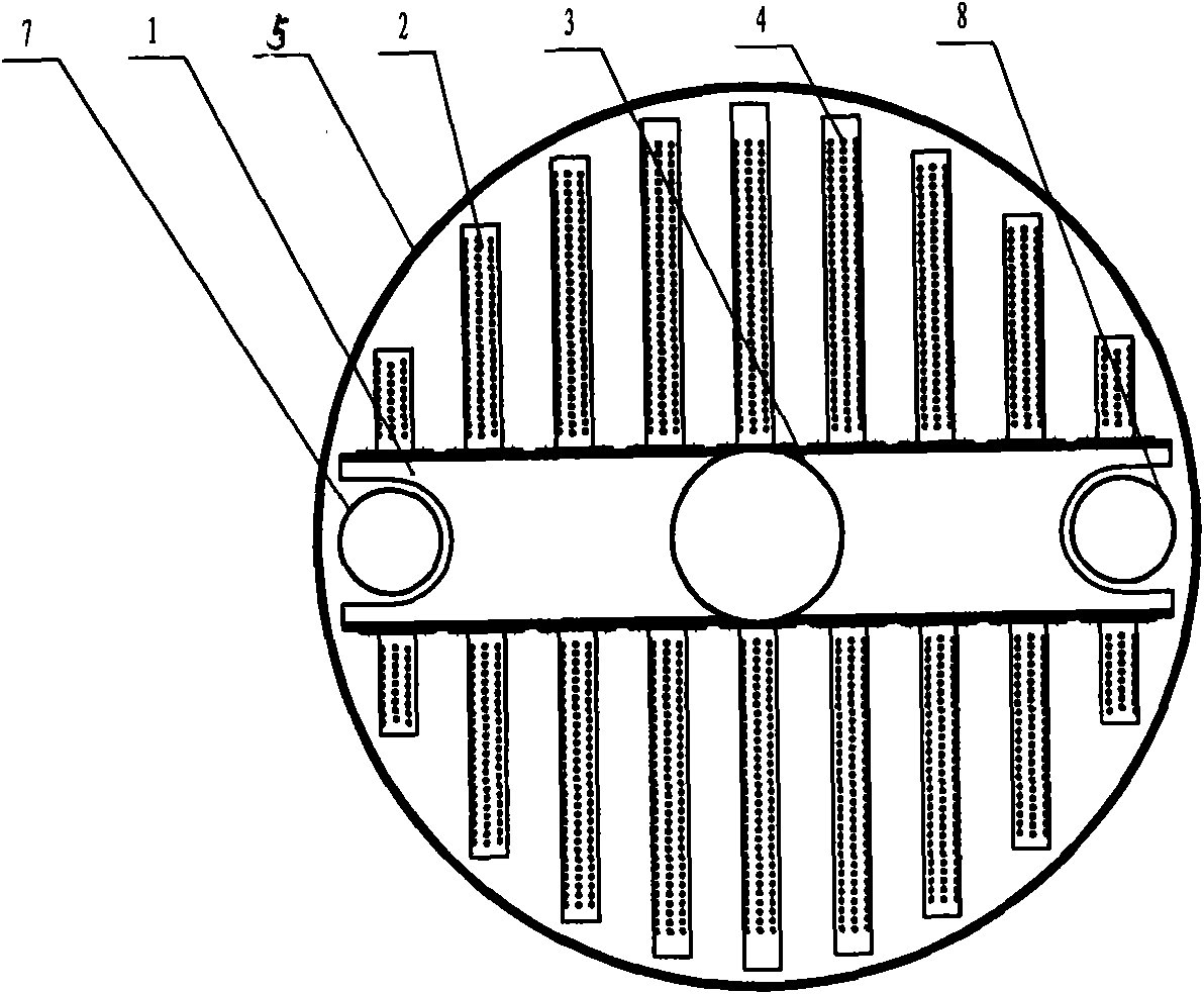
The invention discloses a method for distributing pressure gas in liquid, which is characterized in that after passing through a gas inlet, the pressure gas is first distributed through a sealed cuboid primary tank and then distributed again by small square long pipes on two sides and enters small holes on the small square long pipes to be distributed again. The adopted special equipment comprises a closed tank body (5), which is characterized in that: the sealed cuboid primary tank (1) is arranged in the closed tank body (5); the cuboid primary tank (1) is immersed in reaction solution (6) completely; the small square long pipes (2) which are communicated are distributed on the two sides of the cuboid primary tank; small air holes (4) are uniformly distributed on the small square long pipes (2); the cuboid primary tank (1) is communicated with a round air inlet (3) in the tank body (5); and through the combination, a gas-liquid distribution device is formed in the tank body (5). The equipment is very simple and convenient for installation, low in investment and convenient for overhaul, and is suitable for reconstruction of old desulfurizing tower and more suitable for new tower because the height of the new tower is only 20 to 25 meters, the price is saved by about 30 percent and the desulfuration effect is desirable in the design of a new tower.
Description
A distribution method and special equipment for pressurized gas in liquid Technical field: The invention relates to the technical field of chemical industry, in particular to a method for distributing pressurized gas in a liquid and special equipment, which is suitable for a shift tower for wet desulfurization Background technique: At present, the vast majority of wet desulfurization shift towers basically use packed towers. Packed towers are recognized for their large gas-liquid mass transfer area and high desulfurization efficiency, and are widely used in the industry. In recent years, with the application of all-low shift technology and medium-pressure shift technology, and the use of low-quality high-sulfur coal as the main coal source, it has brought adverse effects on shift gas desulfurization, such as the decrease of purification degree, easy plugging of packing, and Aging and equipment corrosion and other issues. First of all, the degree of purification decreases...
Claims
Login to View More Application Information
Patent Timeline
 Patent Type & AuthorityApplications(China)
IPC IPC(8): B01J10/00B01D53/78B01D53/18
Inventor侯守建张立强
Owner张立强