Round roller screen and driving device
A driving device and rolling technology, applied in the direction of filter screen, solid separation, grille, etc., can solve the problems of difficult replacement, different driving devices, and accelerated screen wear, so as to reduce the use and maintenance cost, reasonable structural design, and prolong The effect of service life
Inactive Publication Date: 2011-06-15
山东鸿达建工集团有限公司
View PDF4 Cites 5 Cited by
- Summary
- Abstract
- Description
- Claims
- Application Information
AI Technical Summary
Problems solved by technology
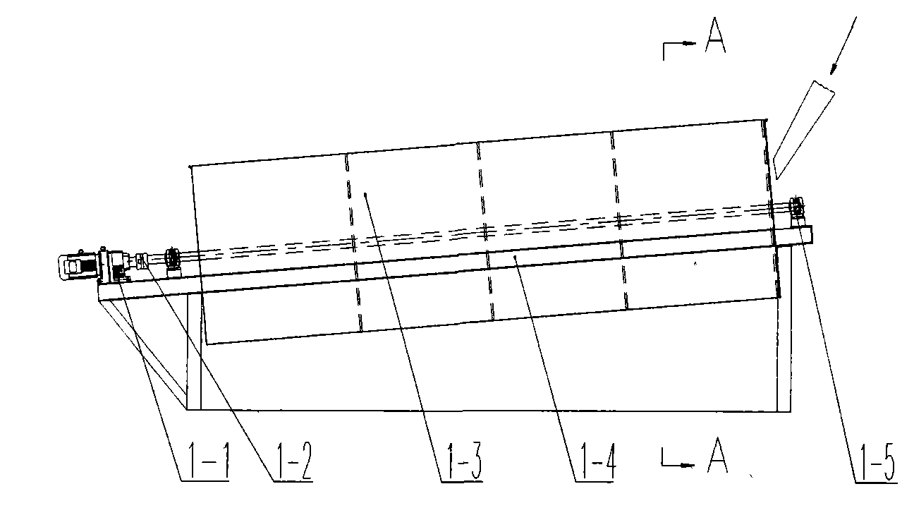
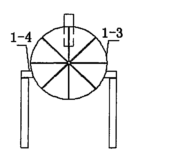
Existing round roller screens are mainly divided into two types, one is shown in Figure 1, which includes a sieve barrel 1-3 mounted on a bracket 1-4, and one end of the bracket 1-4 is equipped with a geared motor 1-1 and a The geared motor 1-1 is connected to the coupling 1-2, and the other end of the bracket 1-4 is installed with a supporting bearing seat 1-5; the internal structure of the screen bucket 1-3 is shown in Figure 3, including the The shaft 3-2 in the barrel 1-3, one end of the shaft 3-2 is connected with the coupling 1-2, and the other end is connected with the support bearing seat 1-5, and the shaft 3-2 is provided with a radial plate 3- 5. The screens of different apertures set on the sieve barrel 1-3 divide the sieve barrel 1-3 into multiple material boxes. From the feed port, there are No. 3 material channel 3-4 and No. 2 material channel 3- 3. No. 1 material channel 3-1, the screen mesh on the material box gradually increases; the above-mentioned circular roller sieve mainly has the following disadvantages: 1), its transmission part is a shaft that directly penetrates the inside of the sieve barrel 1-3, and the two ends are connected by The bearing support is directly connected with the geared motor 1-1 through the coupling 1-2 to drive. Its characteristic is that the sieve barrel 1-3 is supported by a radial plate at the feeding port. , not easy to replace, high maintenance cost, and the shaft directly runs through the sieve body, the torque on the shaft is relatively large, which requires a large shaft diameter; Screening, large materials can be sieved out last, resulting in a long time for large materials to stay in the roller sieve, and the largest aggregates all pass through three kinds of screens, which accelerates the wear of the screens and increases the required driving power; 3) 1. The screen layout adopts a single-layer screen for screening. In the case of ensuring the screening area, the length of the rolling screen needs to be lengthened, which increases the production cost;
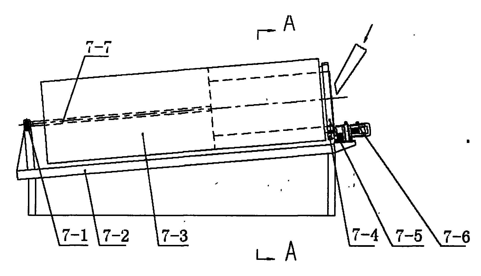
The other one is shown in Figure 5, the screen bucket is the same as the above screen bucket, but the driving device is different, and the driving device includes a bracket 5-1, a reduction motor 5-2, a bearing seat 5-4, a supporting roller 5-5, The rolling ring 5-6; the sieve barrel 5-3 supports the rolling ring 5-6 on the screen body through four supporting rollers 5-5, and the geared motor 5-2 drives the supporting roller 5-5 to pass through the rolling ring 5-6 The driving is completed by the action of friction force. The cost of this kind of equipment is relatively high, the concentricity requirements of the rolling screen are high, and the manufacturing process is complicated. The screen barrel 5-3 is directly placed on the supporting roller through the rolling ring 5-6 on the screen body. Only the retaining wheel is used to prevent movement, and the whole screen body has movement phenomenon. When debugging on the construction site, it is not easy to adjust the balance of the four-wheel friction drive. There is a certain potential safety hazard due to the falling phenomenon of the rolling sieve
Method used
View moreImage
Smart ImageViewing Examples

Examples
Embodiment Construction
Login to view more PUM
 Abstract
The invention relates to a round roller screen and a driving device, and belongs to the technical field of round roller screen structures. The round roller screen is characterized by comprising a bracket and a screen barrel arranged on the bracket, wherein two ends of the bracket are provided with driving devices for driving the screen barrel to rotate; and the driving device comprises an aligning roller bearing arranged at one end of the bracket, the aligning roller bearing is used for connecting a shaft supported in the center of the screen barrel, a speed reducing motor is arranged at the other end of the bracket, the speed reducing motor is connected with and drives a support roller, the support roller is in friction transmission connection with a friction rolling ring arranged on the screen barrel, and the friction resistant rolling ring is linked with the shaft. The round roller screen has reasonable structural design, long service life, good screening effect, low maintenance cost and manufacturing cost, smooth feeding and simple installation and debugging.
Description
A kind of circular roller sieve and driving device technical field The invention relates to a rolling screen and a driving device, and belongs to the technical field of rolling screen structures. Background technique Existing round roller screens are mainly divided into two types, one is shown in Figure 1, which includes a sieve barrel 1-3 mounted on a bracket 1-4, and one end of the bracket 1-4 is equipped with a geared motor 1-1 and a The geared motor 1-1 is connected to the coupling 1-2, and the other end of the bracket 1-4 is installed with a supporting bearing seat 1-5; the internal structure of the screen bucket 1-3 is shown in Figure 3, including the The shaft 3-2 in the barrel 1-3, one end of the shaft 3-2 is connected with the coupling 1-2, and the other end is connected with the support bearing seat 1-5, and the shaft 3-2 is provided with a radial plate 3- 5. The screens of different apertures set on the sieve barrel 1-3 divide the sieve barrel 1-3 into multiple...
Claims
Login to view more Application Information
Patent Timeline
 IPC IPC(8): B07B1/42B07B1/22B07B1/46
Inventor 赵雄志王继红郝敬锋李峰李建国
Owner 山东鸿达建工集团有限公司
- R&D Engineer
- R&D Manager
- IP Professional
Why Eureka
- Industry Leading Data Capabilities
- Powerful AI technology
- Patent DNA Extraction
Try Eureka
Browse by: Latest US Patents, China's latest patents, Technical Efficacy Thesaurus, Application Domain, Technology Topic.
© 2024 PatSnap. All rights reserved.Legal|Privacy policy|Modern Slavery Act Transparency Statement|Sitemap