Multi-spindle U drill gang spindle box and U drill gang high-speed numerical control drilling machine

A spindle box and spindle technology, applied in drilling/drilling equipment, parts of boring machine/drilling machine, boring/drilling, etc., can solve problems such as high efficiency and high quality, and improve hole processing smoothness and performance Good, extended tool life effect

Inactive Publication Date: 2013-06-12
三门峡合鑫机床有限公司
View PDF5 Cites 0 Cited by
  • Summary
  • Abstract
  • Description
  • Claims
  • Application Information

AI Technical Summary

Problems solved by technology

In the current existing technology, there is no U-drill group formed by combining multiple U-drills at close distances at the same time. For porous workpieces that must be processed by U-drills, they can only be processed one by one. This processing method still cannot meet the requirements. High efficiency and high quality work requirements

Method used


Image

  • Multi-spindle U drill gang spindle box and U drill gang high-speed numerical control drilling machine
  • Multi-spindle U drill gang spindle box and U drill gang high-speed numerical control drilling machine
  • Multi-spindle U drill gang spindle box and U drill gang high-speed numerical control drilling machine

Examples


Embodiment 1

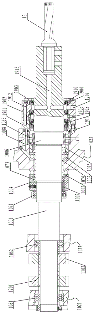
[0027] In this embodiment, the inner ring of the roller bearing located in the shaft hole of the support wall 1023 is a tapered hole (the diameter of the drill port is larger), and the tapered flange matched with the tapered hole is pressed by a specially designed The mechanism tightly presses the tapered flange and the tapered inner ring of the bearing together. The pressing mechanism includes a lock nut between the threaded section and the inner ring of the roller bearing, three 7131 short shafts, a backing ring, a top sleeve, and three 7127 short shafts which are sequentially connected. The lock nut is installed on the threaded section, the three 7131 short shafts are installed in the relief holes of the compression nut 1004, the top sleeve is set between the thrust bearing and the main shaft, and the backing ring is located between the three 7131 short shafts and the top Between the sleeves, three 7127 short shafts are installed in the relief holes of the compression sleev...

Embodiment 2

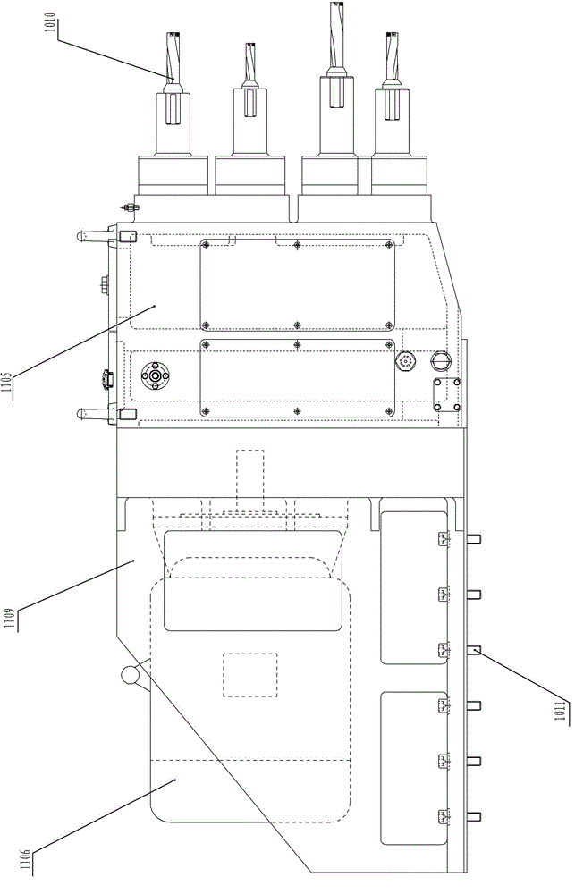
[0078] The longitudinal CNC sliding table includes a base, the lower end of which is fixed on the machine tool base, and the upper end of the base slides with the moving part of the CNC sliding table through guide wheels and guide rails. A controllable workpiece fixture is installed on the vertical CNC slide table for timely adjustment and positioning of the workpiece. One end of the vertical numerical control sliding table is also provided with an adjusting slant iron for positioning or fixing the numerical control sliding table.

[0079] The outer side of the drilling machine also includes a protective casing, and an operation panel is arranged on the casing.

[0080] A chip catcher is installed below the working area of ​​the drill bit and the workpiece, the bottom of the chip catcher has a pulley and a motor is installed at one end thereof, and the pulley is matched and installed on the bottom slideway.

[0081] The water-cooling mechanism is equipped with a cooling pump ...


PUM


Abstract

The invention relates to a multi-spindle U drill gang spindle box and a U drill gang high-speed numerical control drilling machine. The spindle box comprises a box body, a bracket and a motor, wherein at least three layers of supporting walls are arranged vertically in the box body; more than three U drill spindles are respectively arranged in an axle hole of each supporting wall horizontally through a corresponding roller bearing; meanwhile, two side walls of the axle hole of each U drill spindle are respectively provided with a thrust bearing; a cooling mechanism is arranged on the outer end face of the supporting wall closest to a drill bit or the side wall of the box body; the spindle box also comprises auxiliary spindles driven by the U drill spindles; and each spindle and each auxiliary spindle are matched, meshed and in transmission connection through a corresponding layer gear. The drilling machine comprises a machine tool base, a transverse slide table, a longitudinal slide table, a water cooling mechanism, a scrap receiver and the multi-spindle U drill gang spindle box. The invention realizes multi-spindle U drill high-speed high-efficiency drilling processing, can ensure positional accuracy of holes, improves hole processing finish, prolongs the service life of a tool, reduces processing cost in a different form, improves the processing efficiency and the durabilityof the tool, and is innovation in the field of modern high-efficiency special machine tools.

Description

technical field [0001] The invention relates to a high-efficiency multi-axis drilling machine tool, in particular to a multi-axis U-drill group spindle box and a U-drill group high-speed numerical control drilling machine. Background technique [0002] In the traditional machining of hole systems, twist drills and group drills can be widely used in radial drills, vertical drills, multi-spindle combined drilling machines, and even hand electric drills because of their simple structure and low cost. However, with the rapid development of modern mechanical processing to high-speed, high-efficiency, and composite processing, the drilling of composite materials and materials that are difficult to process such as high hardness and high strength has been fundamentally changed due to the invention of the U drill. A twist drill is a tool that drills a circular hole in a workpiece by rotating it relative to a fixed axis. Compared with twist drills, the advantages of U drills are: 1. ...

Claims


Application Information

Patent Timeline
Patent Type & Authority Patents(China)
IPC IPC(8): B23B47/02B23Q5/04B23B39/16
Inventor 徐长群王素琴兀治军葛卫华蔡帅强
Owner 三门峡合鑫机床有限公司
Why Eureka
Try Eureka