Oil slick recovery device
An oil slick recovery and oil slick technology, which is applied in the direction of grease/oily substance/floating matter removal device, liquid separation, separation method, etc., can solve problems such as blockage, bridging, affecting oil collection effect, and failure to solve oil collection work, etc. , to achieve the effect of ensuring liquidity
Inactive Publication Date: 2011-06-15
河北海清大地环保科技有限公司
View PDF6 Cites 13 Cited by
- Summary
- Abstract
- Description
- Claims
- Application Information
AI Technical Summary
Problems solved by technology
However, in these floating oil recovery devices, there is a certain effect on the recovery of light oil and good fluidity, but the recovery of heavy oil, scum, and heavy oil will cause blockage and bridging at the inlet of the floating suction device, affecting the recovery oil effect
Especially when the liquid level in the oil removal tank or the oil pool fluctuates, the oil collection effect is not ideal. In addition, it cannot solve the oil collection work when the temperature is lower than the freezing point of the oil.
Method used
View moreImage
Smart ImageViewing Examples

Examples
Embodiment Construction
Login to View More PUM
 Abstract
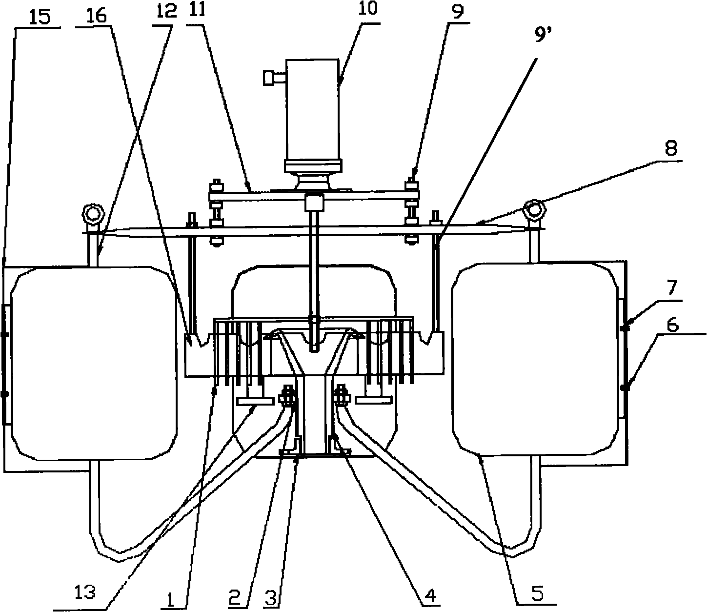
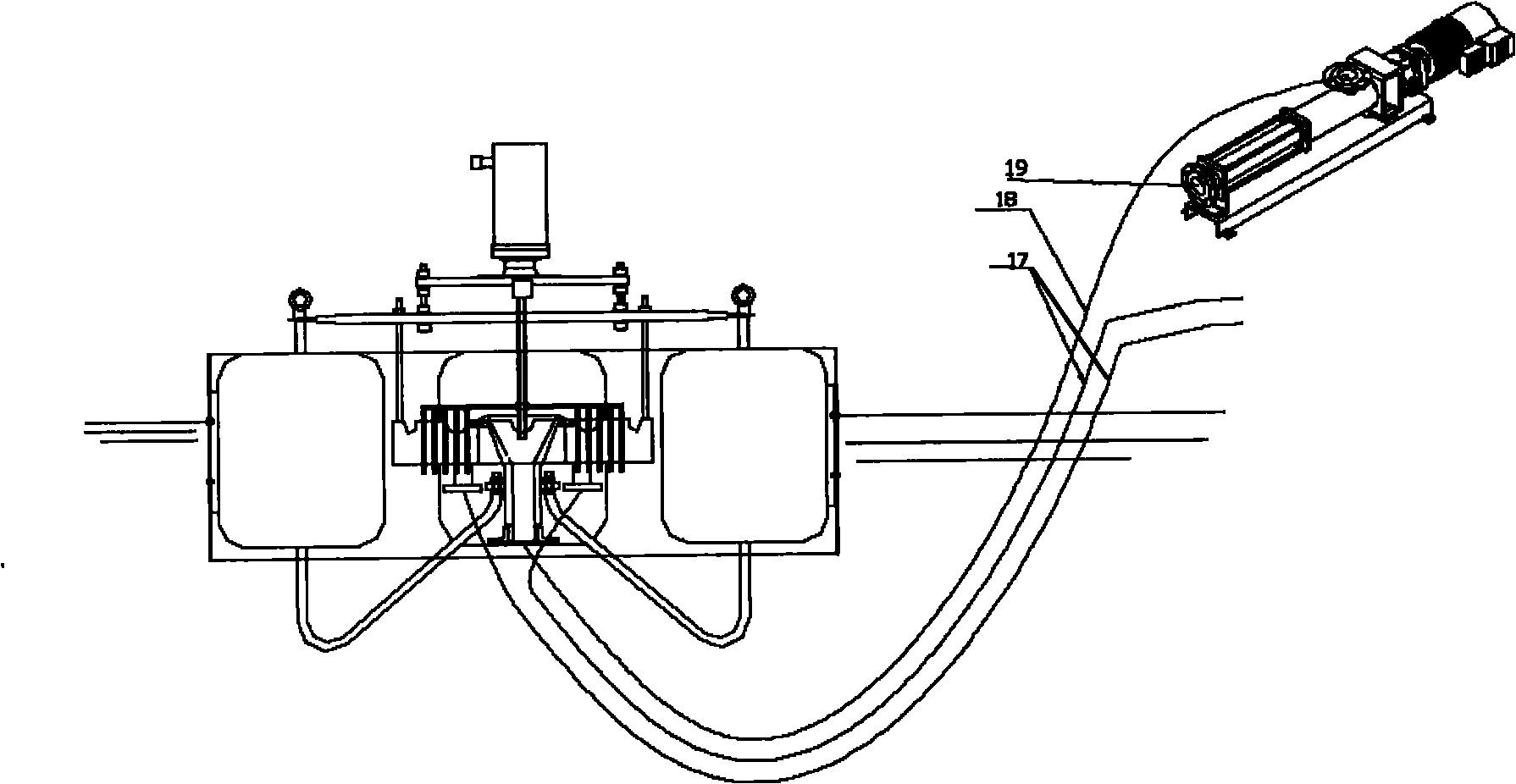
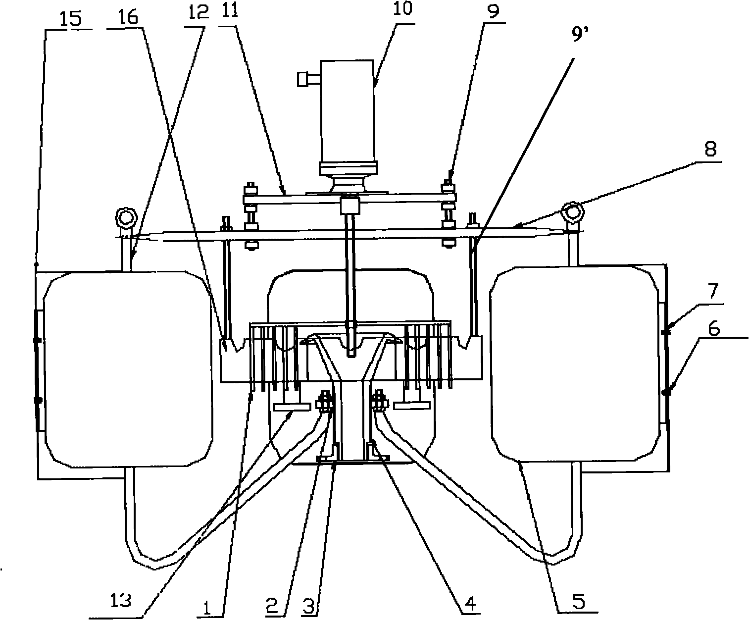
The invention provides an oil slick recovery device, which comprises three buoys (5) and an oil slick suction device (4), wherein the three buoys (5) are fixedly connected to form a triangle by a connecting frame; the oil slick suction device (4) is connected with the three buoys (5), and has a sleeve shape; a taper reamed hole is formed at the oil slick inlet end (41) of the oil slick suction device (4); and the periphery of the taper reamed hole is outwards bent to form an r-shaped weir crest (43). When flowing to the periphery of the weir crest of the oil slick suction device, oil slick or scum can flow into the weir crest without hindrance along the edge of an r shape, and is difficult to accumulate about the weir crest; and the oil slick inlet end of the oil slick suction device adopts the taper reamed hole structure, so the external diameter of the oil slick inlet end and the oil slick is easier to rapidly and forcibly recover.
Description
Oil recovery device technical field The invention relates to a floating oil recovery device. Background technique At present, in the production process of petroleum, petrochemical, steel, food and other fields, a large amount of oily sewage is discharged into various steel storage tanks, dirty oil pools, and sedimentation tanks every day, and the surface contains a large amount of oil slick. The recovery of floating oil mostly adopts oil collection devices such as rope type and cofferdam type. When the water level in the tank or in the oil pool rises to a certain liquid level, the oil slick pump is turned on to suck the floating oil on the surface. Due to the thickness of the slick oil and the height of the liquid level, it is very difficult for the oil collection work. The oil collection work or If it is not carried out in time or the oil collection time is too long, a large amount of water will be collected, which will cause unnecessary troubles for the subsequent work,...
Claims
Login to View More Application Information
Patent Timeline
 IPC IPC(8): C02F1/40
Inventor 白鸿斌
Owner 河北海清大地环保科技有限公司
Features
- R&D
- Intellectual Property
- Life Sciences
- Materials
- Tech Scout
- Unparalleled Data Quality
- Higher Quality Content
- 60% Fewer Hallucinations
Learn More Browse by: Latest US Patents, China's latest patents, Technical Efficacy Thesaurus, Application Domain, Technology Topic, Popular Technical Reports.
© 2025 PatSnap. All rights reserved.Legal|Privacy policy|Modern Slavery Act Transparency Statement|Sitemap|About US| Contact US: help@patsnap.com