Mechanical locking device for packer

A mechanical locking and packer technology, applied in wellbore/well components, earthwork drilling, etc., can solve the problems of inappropriate replacement of multi-flow testers, limited drill collar weight, increased labor intensity, etc. Success rate, reduced labor intensity, good sealing effect

Inactive Publication Date: 2011-06-15
戈宝富
View PDF0 Cites 7 Cited by
  • Summary
  • Abstract
  • Description
  • Claims
  • Application Information

AI Technical Summary

Problems solved by technology

Adding drill collars also increases the labor intensity, and the weight of drill collars is limited. During the test, due to the aging of the multi-stream t

Method used


Image

  • Mechanical locking device for packer
  • Mechanical locking device for packer

Examples


Embodiment Construction

[0013] The present invention will be further described in conjunction with accompanying drawings.

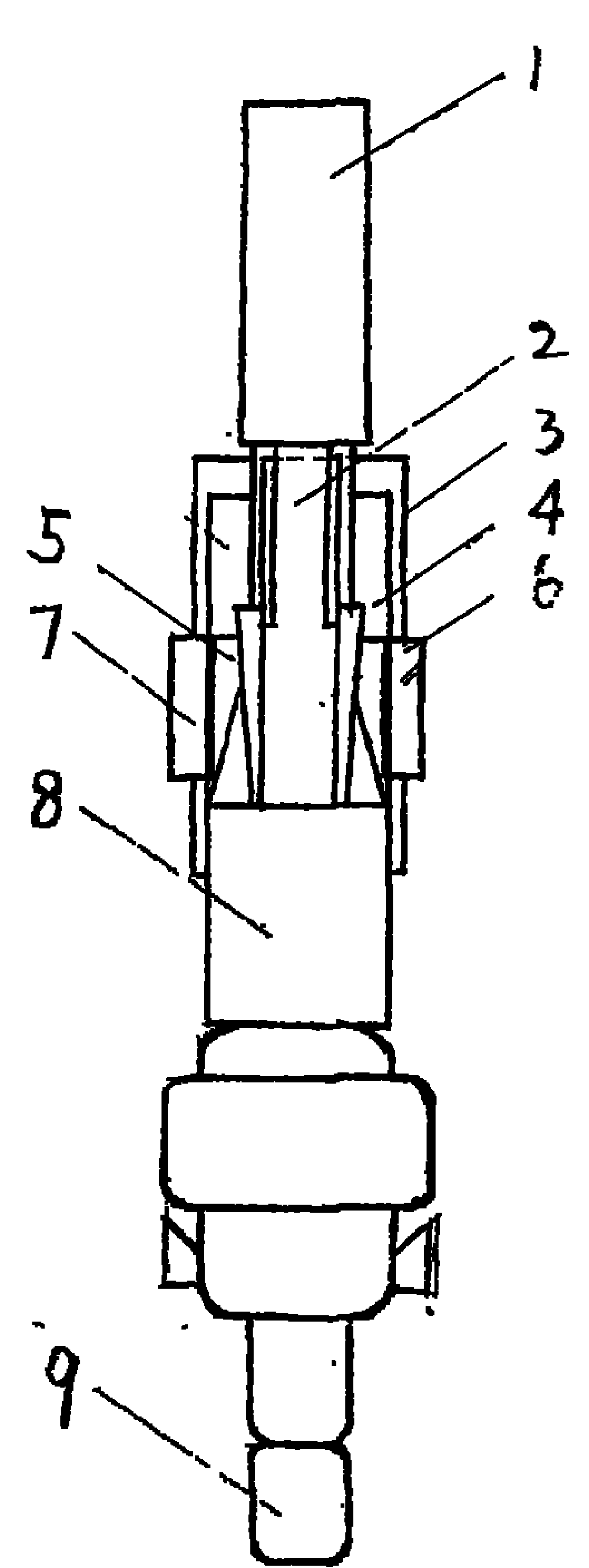
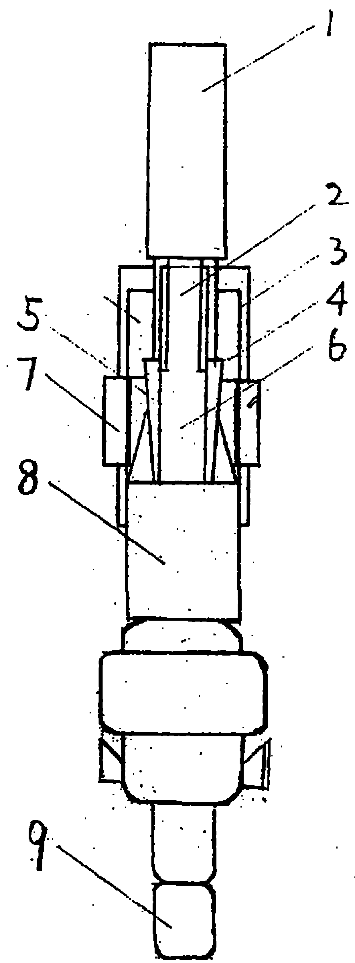
[0014] Such as figure 1 As shown, take the joint test tube as an example.

[0015] Pipe string structure: from bottom to top, the test string is perforating gun, shock absorber, screen, packer, VR, safety joint, mechanical lock, expansion joint, pressure gauge, multi-flow tester, circulation valve , tubing string.

[0016] Drilling down: In the process of lowering the test tube, if there is no resistance, the mechanical locking mandrel will not go down, and the slips in the anchoring mechanism will not move in place.

[0017] Set the packer and open the well: After the test string is lowered to the predetermined position, the sealer is set, and the multi-flow tester test valve and mechanical lock are delayed under the action of the delay mechanism. After the packer is set, At the end of the mechanical locking delay, the reverse slips in the mechanical locking and anchoring me...


PUM


Abstract

A mechanical locking device for locking a packer after set packing comprises two parts, namely an anchor mechanism and a time delay mechanism. The mechanical locking device comprises an upper connector, a spline mandrel, an upper cone, a sleeve, a slip dog, a spline outer barrel, a valve mandrel, an outer barrel, a lower connector and other parts. The time delay mechanism is used for guaranteeing the packer to be operated firstly when in set packing and guaranteeing the lifting force not to act on the packer in a short time when a pipe column is lifted up.

Description

Technical field [0001] The utility model relates to a mechanical locking device for locking a packer after setting, which belongs to the field of petroleum exploitation. Background technique [0002] In oil and gas development, formation testing is widely used as a means to evaluate formations. In conventional well testing, the most widely used is the multi-flow testing tester, which realizes downhole opening and closing of the well by lifting and lowering the string to achieve the purpose of testing wood. In the past, in order to achieve the purpose of not opening the VR bypass or unpacking the packer even if the multi-flow tester was transposed during well operation, many auxiliary tools were equipped in the test string, such as hydraulic locking, telescopic joints, drill collars, etc. Adding drill collars also increases the labor intensity, and the weight of drill collars is limited. During the test, due to the aging of the multi-stream tester’s displacement spring and ...

Claims


Application Information

Patent Timeline
IPC IPC(8): E21B23/06
Inventor 吴勇
Owner 戈宝富
Why Eureka
Try Eureka