
Constant power dual laterolog equipment circuit and control method thereof

A dual laterolog and constant power technology, which is applied in measurement, earthwork drilling, wellbore/well components, etc., can solve the problem of small dynamic range of measurement and achieve the effect of enhanced load capacity

Inactive Publication Date: 2011-06-15
XIAN WELL LOGGING ENERGY TECH
View PDF8 Cites 2 Cited by
  • Summary
  • Abstract
  • Description
  • Claims
  • Application Information

AI Technical Summary

Problems solved by technology

[0002] The traditional resistivity logging tool adopts the constant current working mode, and the conductivity logging tool adopts the constant voltage working mode. When the formation resistivity changes, the former only responds to this change with voltage, and the latter only responds to this change with current. Therefore, Measurement dynamic range is small

Method used


Image

  • Constant power dual laterolog equipment circuit and control method thereof
  • Constant power dual laterolog equipment circuit and control method thereof
  • Constant power dual laterolog equipment circuit and control method thereof

Examples


Embodiment Construction

[0015] The present invention will be described in detail below in conjunction with the accompanying drawings and specific embodiments.

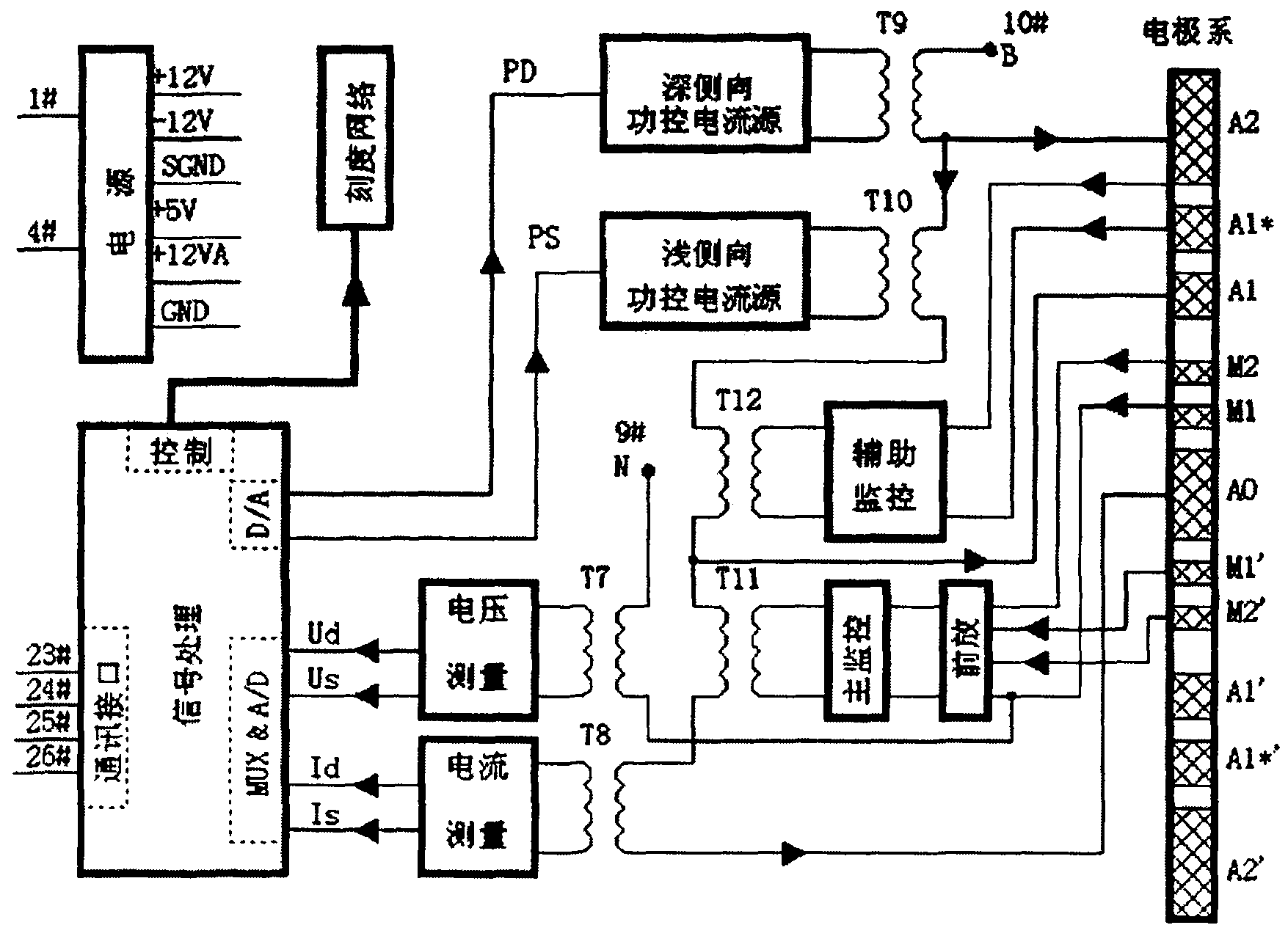
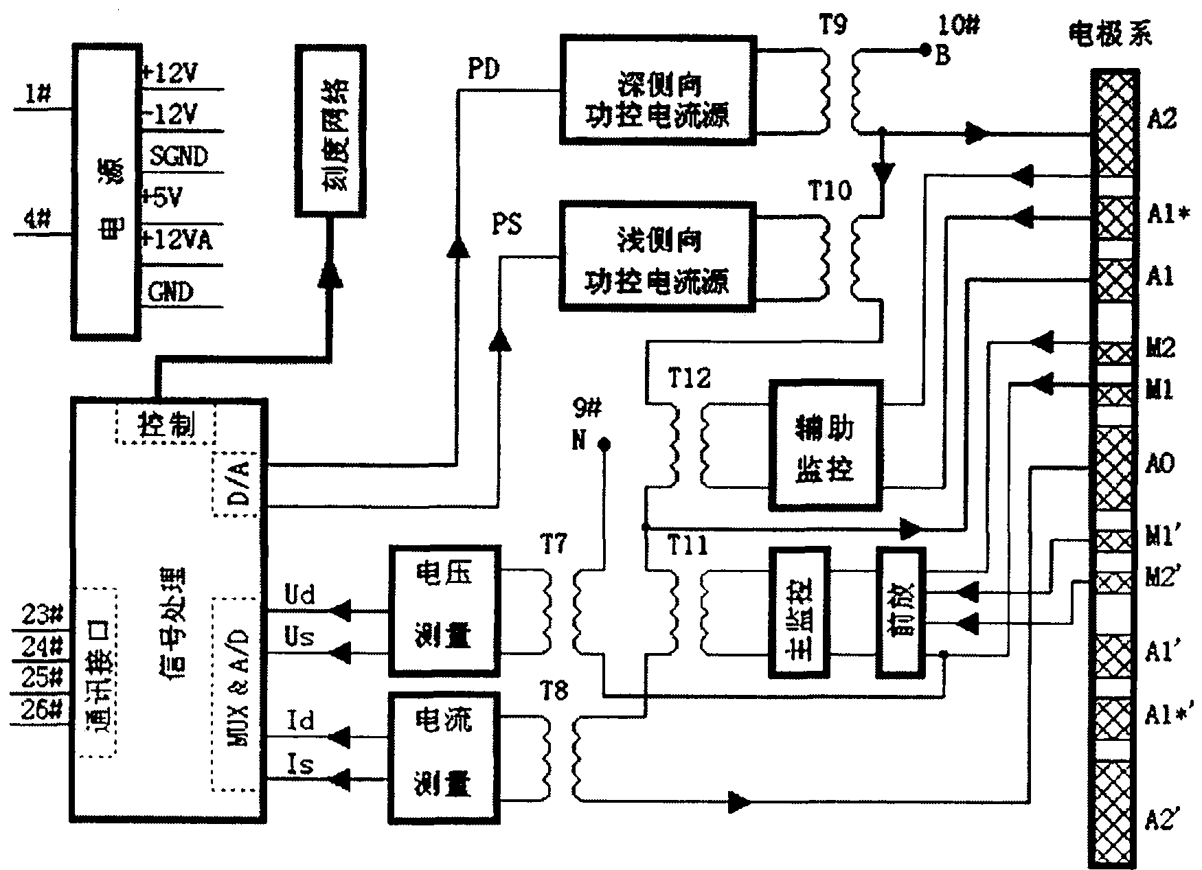
[0016] see Figure 1~2 , the present invention is made up of digital circuit and analog circuit, and analog circuit comprises deep power control current source circuit, shallow power control current source circuit, main monitoring circuit, auxiliary monitoring circuit, voltage measuring circuit, current measuring circuit, scale circuit, and digital circuit comprises Multi-way switch, programmable gain, D / A converter, A / D converter, microcontroller, timer, digital control board, multi-way switch, programmable gain, D / A converter, A / D converter, timer It is connected with the single chip microcomputer and the digital control board, and the measured analog signals are output to the programmable gain through the multi-channel switch, and then converted and digitized by the A / D converter; the analog circuit and the digital circuit are passed throu...


PUM


Abstract

The invention relates to a constant power dual laterolog equipment circuit and a control method thereof. The conventional resistivity logging equipment adopts a constant current working way, conductivity logging equipment adopts a constant voltage working way, and the conventional resistivity logging equipment only has the change of voltage response and the conductivity logging equipment only has the change of current response when a formation resistivity is changed, so that measuring dynamic ranges are narrow. The constant power dual laterolog equipment circuit consists of a digital circuit and an analog circuit, wherein the analog circuit comprises a deep power control current source circuit, a shallow power control current source circuit, a main monitoring circuit, an auxiliary monitoring circuit, a voltage measurement circuit, a current measurement circuit and a scale circuit; and the digital circuit comprises a multi-way switch, a program-controlled gain, a digital to analog (D / A) converter, an analog to digital (A / D) converter, a singlechip, a timer and a digital control panel. In the constant power dual laterolog equipment circuit, a singlechip control technology is adopted, and a clock produces synchronous deep and shallow lateral working frequencies when the singlechip is operated; an oscillating source circuit and a square wave generating circuit in the conventional designs are omitted; and deep and shallow lateral current sources adopt a high power amplifier integrated circuit to greatly improve the load capacity.

Description

technical field [0001] The invention relates to a circuit of a constant power double lateral logging instrument and a control method thereof. technical background [0002] The traditional resistivity logging tool adopts the constant current working mode, and the conductivity logging tool adopts the constant voltage working mode. When the formation resistivity changes, the former only responds to this change with voltage, and the latter only responds to this change with current. Therefore, The measurement dynamic range is small. The main feature of the constant power dual laterolog tool is to keep the power of the main current source constant during the logging process in order to obtain the largest possible measurement dynamic range and high measurement accuracy. Contents of the invention [0003] The technical problem solved by the present invention is to provide a constant power dual laterologging instrument circuit and a control method thereof. [0004] For solving ab...

Claims


Application Information

Patent Timeline
Patent Type & Authority Applications(China)
IPC IPC(8): E21B47/00E21B49/00
Inventor 肖江涛
Owner XIAN WELL LOGGING ENERGY TECH
Learn More