

Submerged electric pump for well
A submersible electric pump and pump body technology, applied in the direction of the pump, the components of the pumping device for elastic fluid, the pump device, etc., can solve the problems affecting the stability and service life of the electric pump, deformation, deformation of the connection seat, etc. Achieve the effect of preventing the impeller from floating, improving the service life and preventing bending deformation
Active Publication Date: 2011-06-15
TAIZHOU YONGXIN PUMP IND
View PDF5 Cites 0 Cited by
- Summary
- Abstract
- Description
- Claims
- Application Information
AI Technical Summary
Problems solved by technology
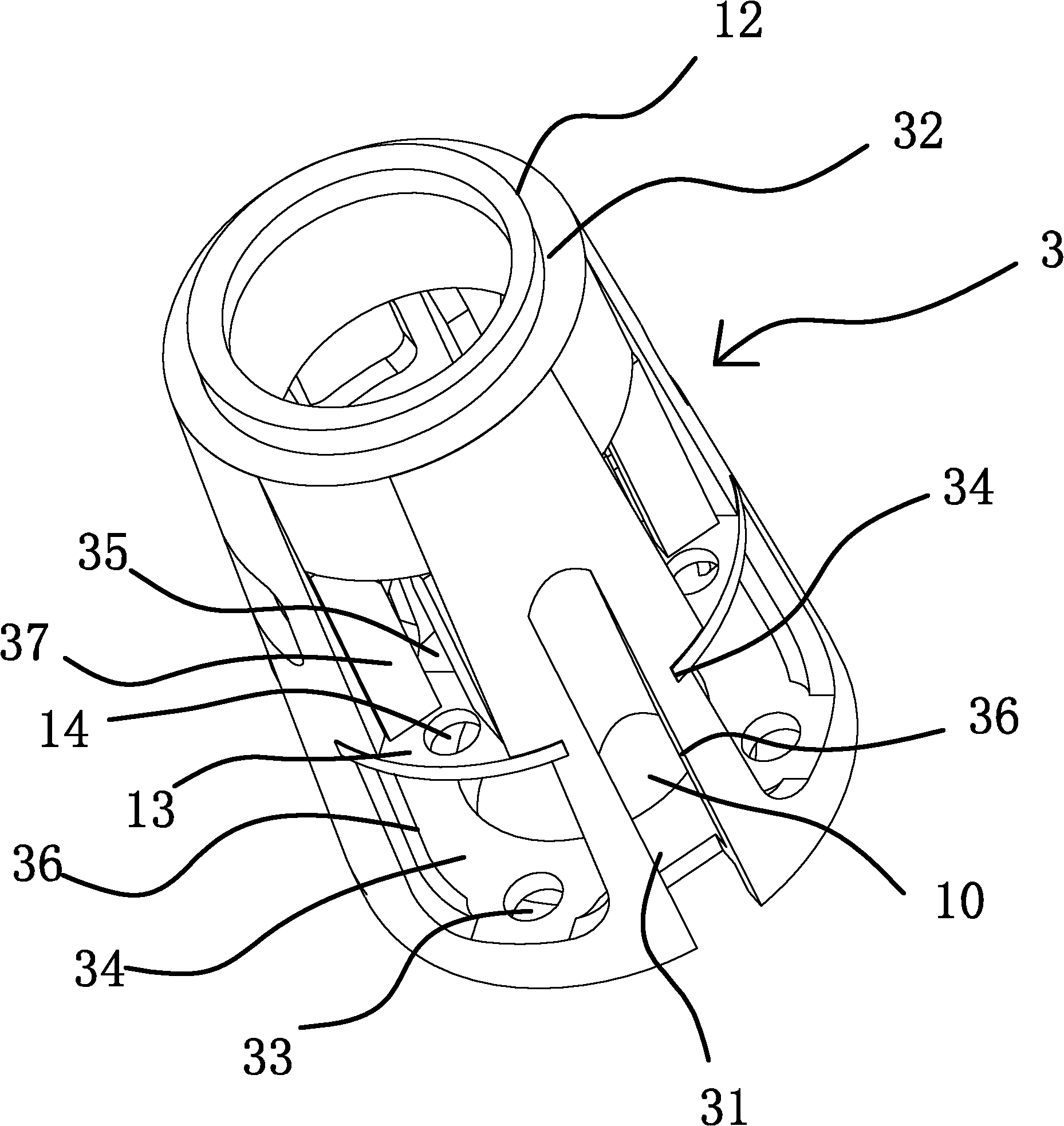
The existing connecting base is only provided with a first mounting hole and a plurality of second mounting holes for the passage of the motor cable on its side wall. The second mounting hole is mainly for the convenience of installation for connecting the connecting base and the housing. Bolts, and in order to facilitate the passage of the main shaft, the inside of the connecting seat is hollow and only supported by the side wall. At the same time, submersible pumps for wells are generally buried deep underwater. Deformation occurs, especially the side wall part of the connection seat between the first mounting hole and the second mounting hole is prone to deformation, which affects the stability and service life of the entire electric pump
Method used
View moreImage
Smart ImageViewing Examples


Examples
Embodiment Construction
Login to View More PUM
 Abstract
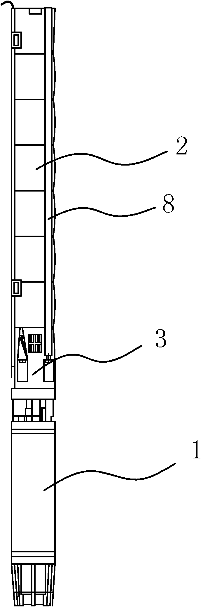
The invention provides a submerged electric pump for a well, and belongs to the technical field of machinery. The submerged electric pump provided by the invention is used for solving the problems of less bearing capacity, low efficiency and high production cost of the existing submerged electric pump for a well. The submerged electric pump for the well comprises a shell, a motor, a main shaft and a pump body, wherein the main shaft is connected with a motor rotary shaft; the pump body consists of a plurality of pump units, and a connecting seat is connected between the pump body and the shell; one end surface of the connecting seat is provided with bolt holes, and the side wall of the connecting seat is provided with first mounting holes which are corresponding to the bolt holes; third mounting holes are arranged between any two adjacent first mounting holes; each pump unit is composed of a guide blade shell of a tubular integral structure and a vane wheel which is placed in the guide blade shell; the guide blade shell is provided with a shaft sleeve which is made of a nitrile rubber buna material; and two long side edges of each first mounting hole and each third mounting hole are provided with reinforcing ribs which are bent toward the interior of the connecting seat. The submerged electric pump for the well has the advantages of great bearing capacity, high efficiency and low production cost.
Description
A kind of submersible electric pump for well technical field The invention belongs to the technical field of machinery, and relates to a pump, in particular to a well submersible electric pump. Background technique Existing submersible electric pumps for large flow wells generally consist of a casing, a motor installed in the casing, a main shaft and a pump body, wherein the pump body is composed of multiple pump units connected, and the pump body and the casing are connected by a The seat is connected together, and the pump unit is composed of an impeller and a vane casing, and the impeller is placed in the vane casing. The existing connecting base is only provided with a first mounting hole and a plurality of second mounting holes for the passage of the motor cable on its side wall. The second mounting hole is mainly for the convenience of installation for connecting the connecting base and the housing. Bolts, and in order to facilitate the passage of the main shaft, th...
Claims
Login to View More Application Information
Patent Timeline
 Patent Type & AuthorityApplications(China)
IPC IPC(8): F04D13/08F04D29/40
Inventor张子林
OwnerTAIZHOU YONGXIN PUMP IND