Intelligent electrohydraulic flow servo valve

A servo valve, intelligent technology, applied in the direction of servo motor components, fluid pressure actuators, mechanical equipment, etc., can solve the static indicators such as servo valve symmetry, linearity, etc., which have not been significantly improved, position sensor parameters and closed-loop control Parameters cannot be adjusted by themselves, there is no intelligent fault diagnosis, self-adaptation and other problems, to achieve the effect of realizing intelligent control and self-adaptation ability, flexible setting and adjustment of control parameters, and improving anti-interference ability

Active Publication Date: 2011-06-15
陈镇汉 +2
View PDF4 Cites 18 Cited by
  • Summary
  • Abstract
  • Description
  • Claims
  • Application Information

AI Technical Summary

Problems solved by technology

This valve has a simple structure and high static precision, but because the pre-stage is directly connected to the main valve core, the motion inertia is large, so the natural frequency is low, the dynamic performance of the valve is low, and the electric power consumption of the pre-stage is large. The volume is also relatively large
Double nozzle baffle electric feedback two-stage electro-hydraulic flow servo valve, such as the Moog D765 servo valve, is based on the force feedback two-stage electro-hydraulic flow servo valve, and the displacement of the two-stage slide valve is converted into a position by a displacement sensor The electrical feedback signal is combined with the input command signal to perform closed-loop control. Since the loo...

Method used


Image

  • Intelligent electrohydraulic flow servo valve
  • Intelligent electrohydraulic flow servo valve
  • Intelligent electrohydraulic flow servo valve

Examples


Embodiment Construction

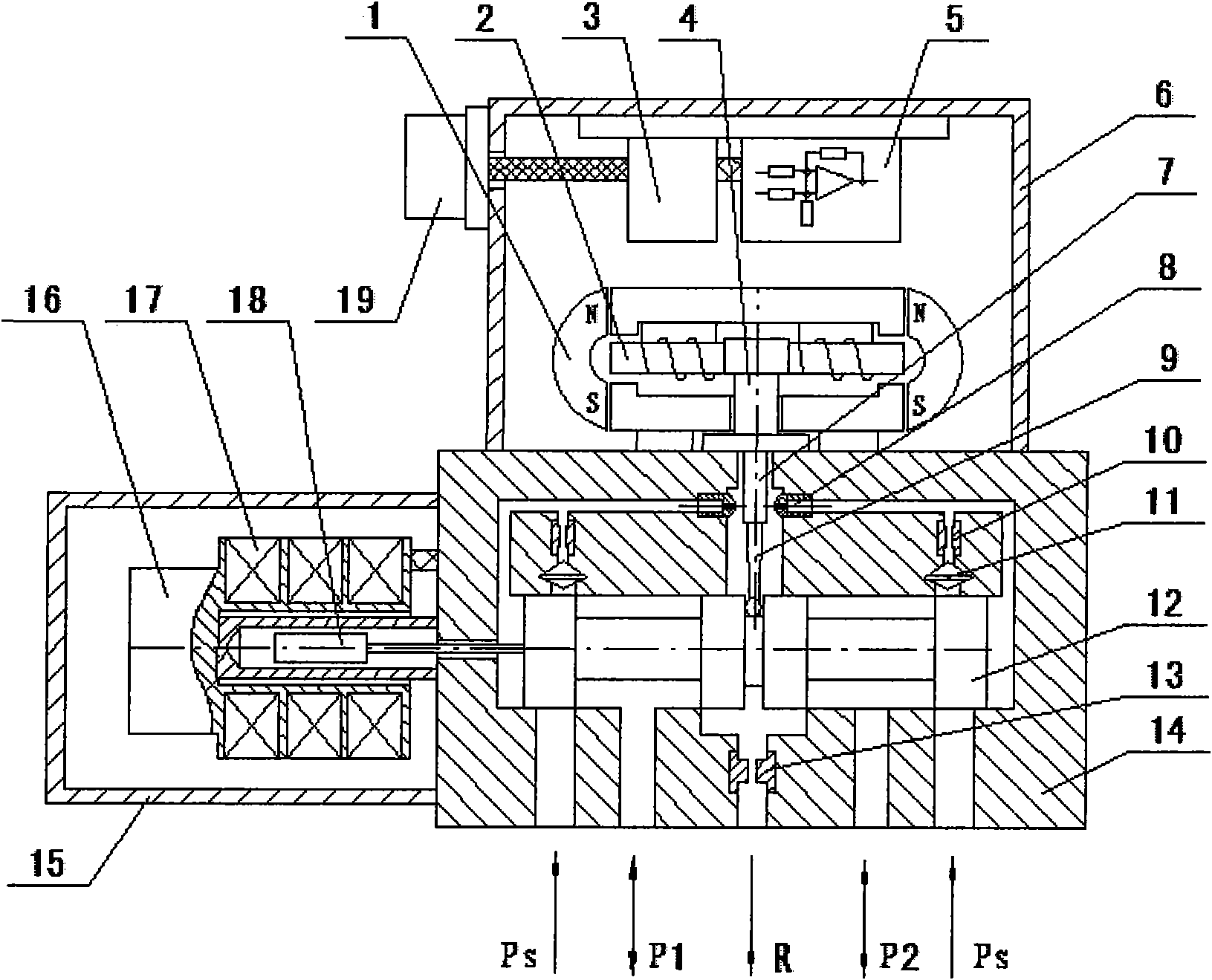
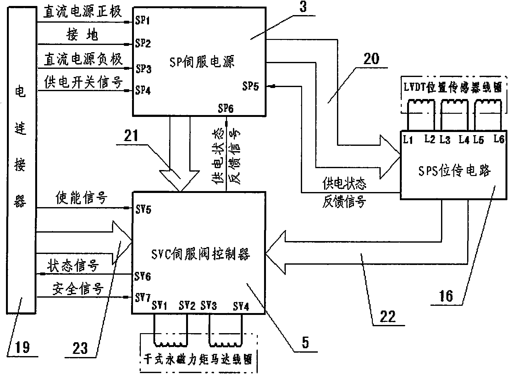
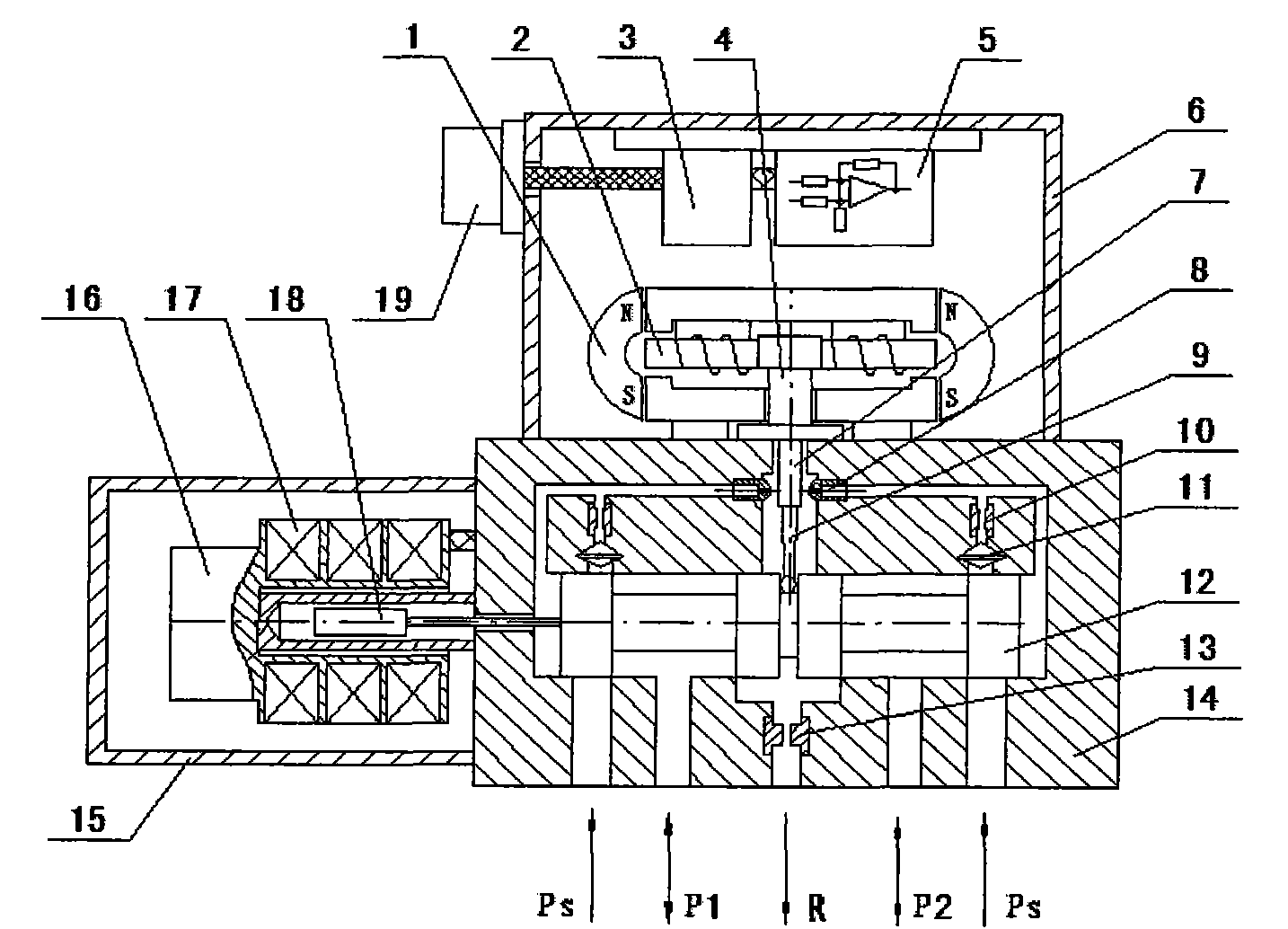
[0018] exist figure 1 In the shown embodiment, the SP servo power supply 3 and the SVC servo valve controller 5 are installed and fixed on the upper cover 6 of the electro-hydraulic flow servo valve with screws; the dry permanent magnet torque motor 1 and the gear assembly 2 are arranged on the SP The lower end of the servo power supply 3 and the SVC servo valve controller 5 is installed and fixed on the valve body 14 below the SP servo power supply 3 and the SVC servo valve controller 5; The flow chamber and the control chambers at both ends of the force feedback centering slide valve 12 are connected; the force feedback centering slide valve 12 is respectively connected with the high pressure oil chamber, the load oil chamber and the oil return chamber through the oil circuit; the dry permanent magnet torque motor The gear assembly 2 in 1 is connected with the feedback lever 9 and the force feedback centering slide valve 12; the iron core 18 in the LVDT high-precision positi...


PUM


Abstract

The invention discloses an intelligent electrohydraulic flow servo valve. The intelligent electrohydraulic flow servo valve is characterized in that: a servo power (SP) and a servo valve controller (SVC) are arranged in a top cover of the electrohydraulic flow servo valve; a dry permanent magnet torque motor, and a baffle assembly is arranged on a valve body; a double nozzle flapper is connected with a high-pressure oil cavity, an overflow cavity, and control cavities at two ends of a force feedback centering slide valve through an oil path respectively; the force feedback centering slide valve is connected with the high-pressure oil cavity, a load cavity and an oil return cavity through the oil path respectively; the baffle assembly of the dry permanent magnet torque motor is connected with a feedback rod and the force feedback centering slide valve; an iron core of a linear variable differential transformer (LVDT) is connected with the force feedback centering slide valve; an SPS position transmission circuit is directly fixed on the side of a coil framework of the LVDT; and the high-precision LVDT, and the SPS position transmission circuit are arranged in an outer cover on one side of the valve body.

Description

technical field [0001] The invention relates to an electro-hydraulic flow servo valve, in particular to an electro-hydraulic flow servo valve integrating high integration, intelligent fault diagnosis, high precision and high dynamic response. Background technique [0002] The electro-hydraulic servo valve is not only an electro-hydraulic conversion element, but also a power amplification element, which can convert a low-power electrical signal input into a high-power hydraulic energy output. In the electro-hydraulic servo system, the electrical part is connected with the hydraulic part to realize the conversion and amplification of the electro-hydraulic signal. The electro-hydraulic servo valve is the core control element of the electro-hydraulic servo system, and its performance and reliability will directly affect the performance and reliability of the electro-hydraulic servo control system. With the rapid development of modern science and technology, the new generation o...

Claims


Application Information

Patent Timeline
IPC IPC(8): F15B13/044
Inventor 陈镇汉陈阳陈宜
Owner 陈镇汉
Why Eureka
Try Eureka