
High-power stepless transmission

A continuously variable transmission, high-power technology, applied in the direction of belt/chain/gear, mechanical equipment, transmission device, etc., can solve the problem of not being able to meet the high-speed and high-power transmission of power, the tangent point between the tooth chain and the rotation plane is not fixed, and has not been effectively obtained. Solve problems such as to achieve the effect of improving transmission power, improving work reliability and wide application range

Inactive Publication Date: 2011-06-15
刘爱诗
View PDF0 Cites 27 Cited by
  • Summary
  • Abstract
  • Description
  • Claims
  • Application Information

AI Technical Summary

Problems solved by technology

The fundamental way to realize high-power continuously variable transmission should be gear transmission, but this problem has not been effectively solved
The disadvantages of this structure are: first, the locking slider of the planetary gear one-way clutch is easy to slide, and cannot transmit large power; In the non-meshing state, the corresponding position between the tooth and the tooth groove causes the two to collide and interfere during the meshing process. Even if the backlash with spring return is adopted, the collision interference cannot be eliminated, and the backlash will also be caused by the backlash. The third is that the rotation plane surrounded by multiple planetary gears is not a circle but a polygon, which leads to the unfixed tangent point between the tooth chain and the rotation plane during work, causing radial runout of the tangent point, causing the tooth chain Vibrates and causes periodic changes in the tightness of the tooth chain
These cannot meet the needs of high-speed and high-power transmission power
At present, automotive continuously variable transmissions can only be used in small cars with small and medium displacement.

Method used


Image

  • High-power stepless transmission
  • High-power stepless transmission
  • High-power stepless transmission

Examples


Embodiment Construction

[0026] The present invention will be further described below in conjunction with drawings and embodiments.

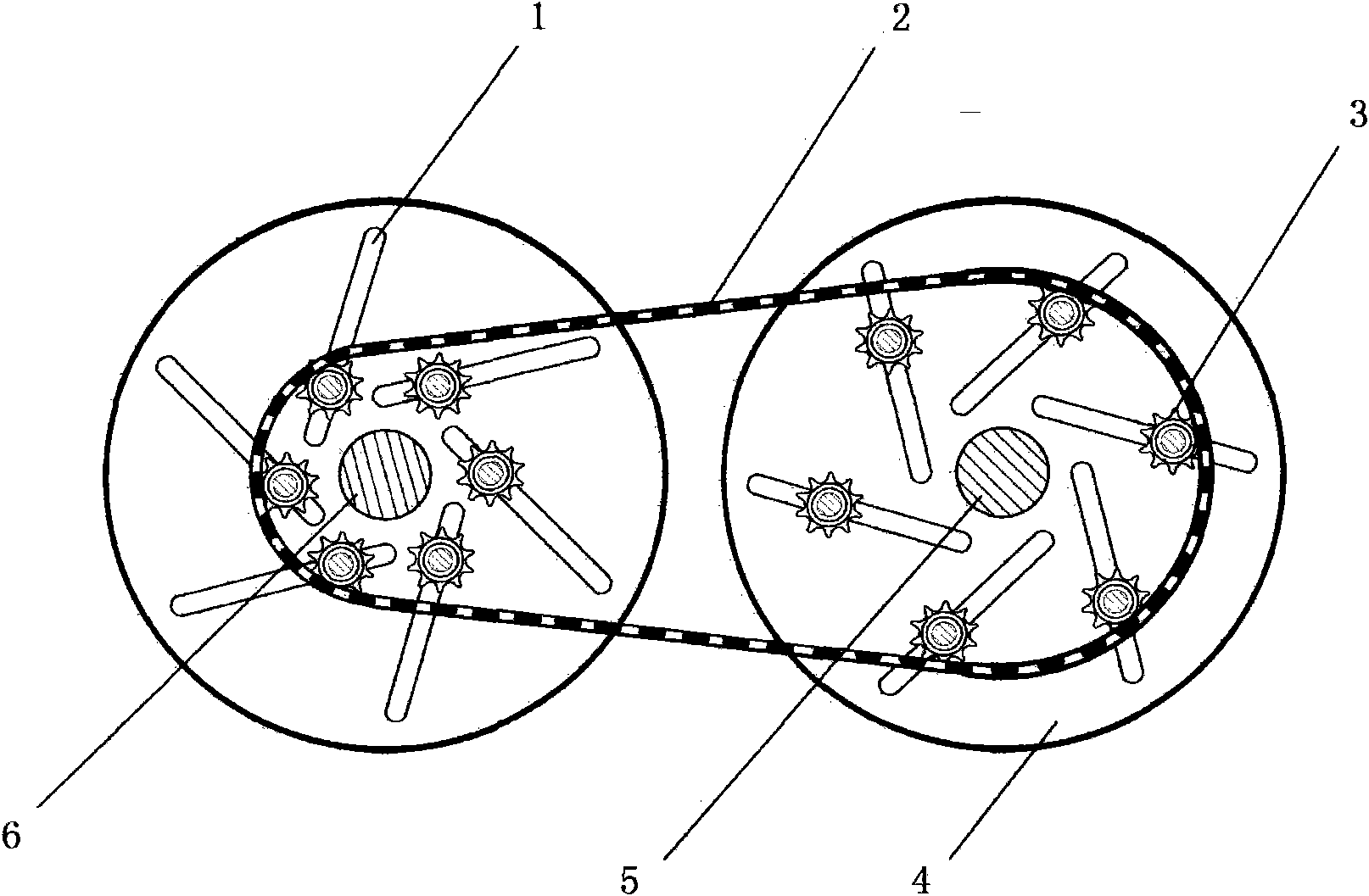
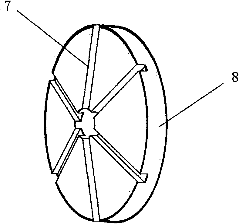
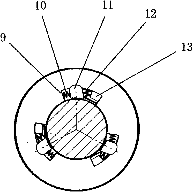
[0027] See figure 1 with figure 2 , the driving drive shaft (5) and the driven drive shaft (6) are equipped with a speed regulating disc (4) and a driving wheel (8), the driving wheel is located at the back of the speed regulating disc, and the shaft of the planetary gear (3) passes through The oblique slot hole (1) on the speed control disc is located in the radial chute (7) of the drive wheel, and the tooth chain (2) surrounds the planetary gear and connects the main and driven transmission shafts through the speed control disc and the drive wheel . See image 3 , a clutch chamber (9) is provided in the shaft hole of the planetary gear, and a self-locking pendulum pin (11) is provided in the chamber. The supporting point is the center of circle to swing. The length of the self-locking pendulum pin is greater than the radial distance between its supporting point ...


PUM


Abstract

The invention relates to a tooth chain type stepless transmission for an automobile. A tooth chain is arranged around a plurality of planetary gears which can unidirectionally rotate; all the planetary gears can move in a corresponding radial chute on a drive wheel; and stepless transmission is realized by changing the revolution diameter of the planetary gears. An unlocking key is arranged in a one-way clutch of each planetary gear; and when the tooth chain and the planetary gears are meshed and separated, the unlocking key can be driven so that the clutch is maintained in a one-way locking state or unlocking state. The invention breaks through the traditional theory that the stepless transmission is only friction power transmission, solves the problem of carrying out stepless transmission by utilizing a gear, can effectively improve the transfer power of the stepless transmission and has the advantages of large force transmission, high rotating speed, stable running, reliable work, and the like.

Description

technical field [0001] The invention belongs to the field of mechanical transmissions, in particular to a high-power continuously variable transmission for automobiles. Background technique [0002] Continuously variable speed is the ultimate goal of automotive transmission development. The principle of the existing continuously variable transmission is all the way of friction transmission of power, and the transmitted power is relatively small. The fundamental way to realize high-power continuously variable transmission should be gear transmission, and this problem has not been effectively solved. For example, a sliding toothed belt type continuously variable transmission, the sliding plate on the toothed belt can be embedded in the radial chute on the driving wheel to play the role of tooth transmission, and the sliding plate can move in the chute to change the driving radius to realize infinitely variable speed . Due to this structure, when the sliding plate and the ch...

Claims


Application Information

Patent Timeline
Patent Type & Authority Applications(China)
IPC IPC(8): F16H9/24
CPCF16H9/10
Inventor 刘爱诗季丹刘芳刘少成刘博阳
Owner 刘爱诗
Learn More