
Mechanical synchronous crank labor-saving torque-increasing mechanism

A mechanical synchronization and crank technology, applied in mechanical equipment, belts/chains/gears, transmissions, etc., can solve the problem of not being able to increase torque at the same speed, and achieve the effects of reducing input power, reducing pollution emissions, and saving energy

Inactive Publication Date: 2011-06-15
朱瑞星
View PDF0 Cites 2 Cited by
  • Summary
  • Abstract
  • Description
  • Claims
  • Application Information

AI Technical Summary

Problems solved by technology

Its highest efficiency is only 98%, that is, at least 2% of energy consumption is lost, and environmental noise pollution is not included, so it cannot achieve the same speed increase of torque

Method used


Image

  • Mechanical synchronous crank labor-saving torque-increasing mechanism
  • Mechanical synchronous crank labor-saving torque-increasing mechanism
  • Mechanical synchronous crank labor-saving torque-increasing mechanism

Examples


specific Embodiment approach 1

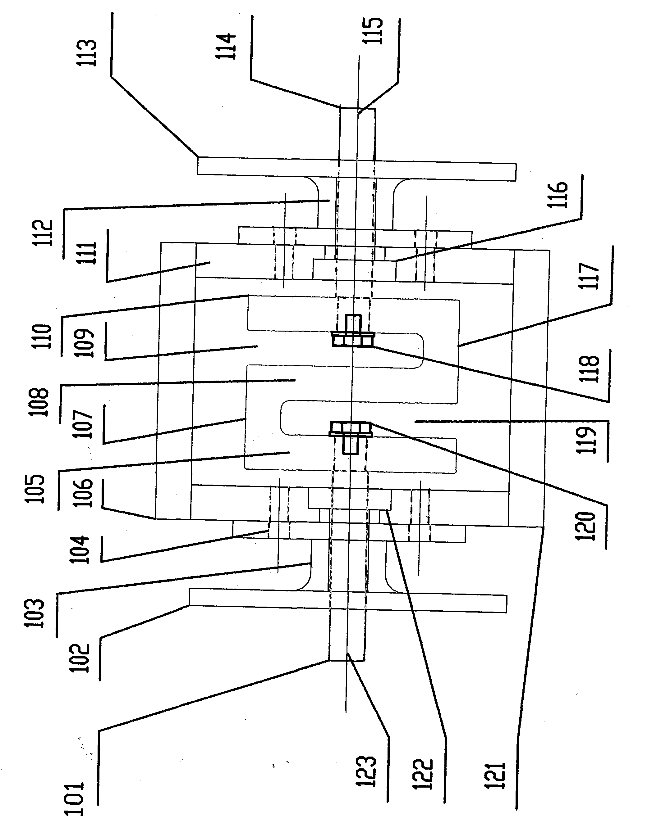
[0041] Specific implementation plan 1: Basic single-stage coaxial input and output mechanical synchronous crank labor-saving torque increasing mechanism The basic single-stage coaxial input and output mechanical synchronous crank torque increasing mechanism consists of six basic mechanisms, fixed mechanism, input mechanism, torque increasing mechanism, transmission Mechanism, dynamic balance mechanism, output mechanism. The input and output terminals of this basic scheme are not divided, that is, the input and output can be connected casually, which is also a major advantage of this scheme.

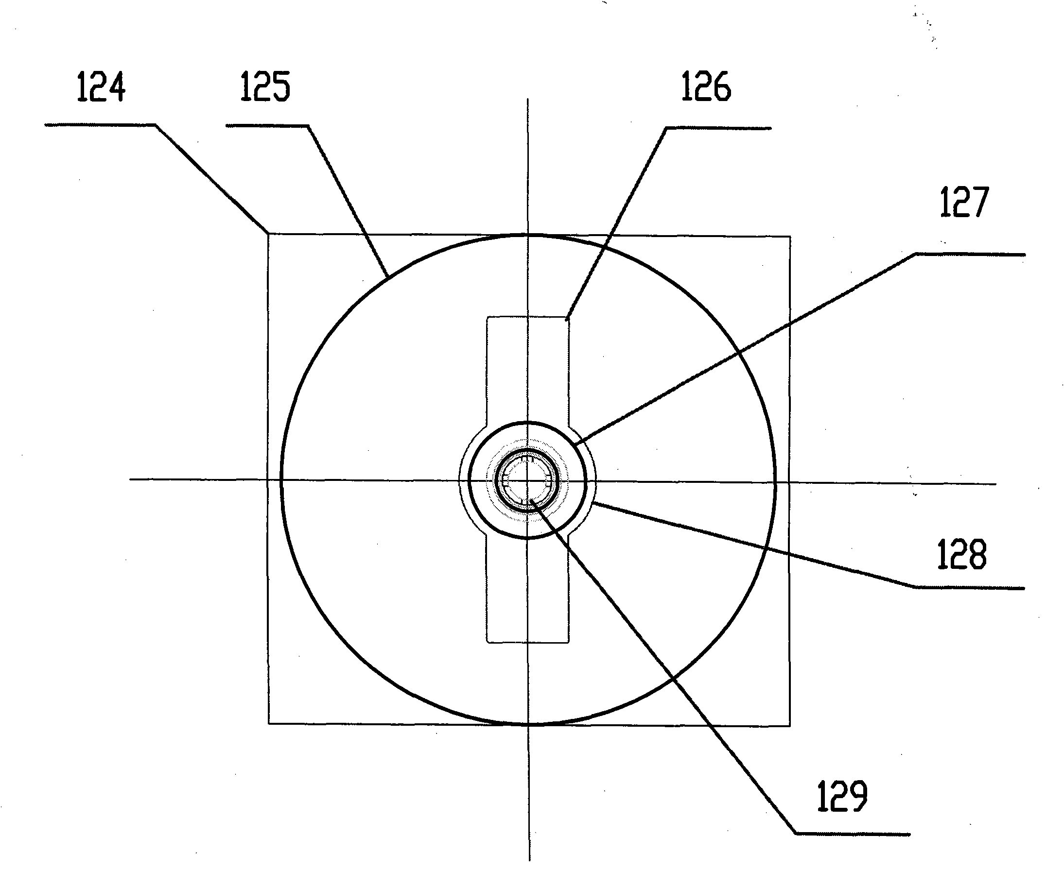
[0042] If 101 is the input shaft, then 123 is just the input connection keyway. The input connection of this structural diagram is a coaxial connection, the connection is fixed flange 102 (namely 125), 103 is the sealing groove of the input shaft 101, and 104 is the crimping bolt hole between the input connecting flange and the input fixing plate. The input shaft 101 is connected with th...

specific Embodiment approach 2

[0047] Specific implementation plan 2: double-stage series connection input and output mechanical synchronous crank labor-saving and torque-increasing mechanism

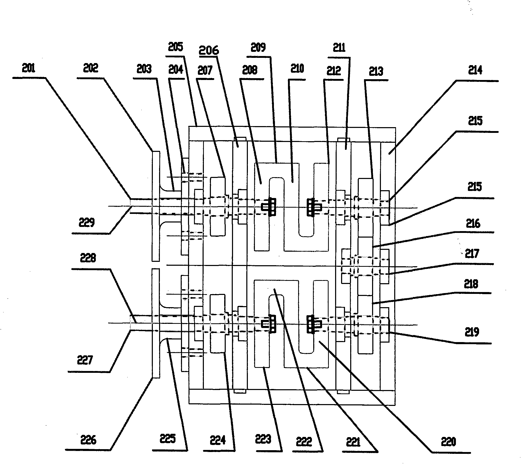
[0048] The two-stage series series input and output mechanical synchronous crank torque increasing mechanism is composed of eight basic mechanisms, the fixed mechanism, the input mechanism, the first-level torque increasing mechanism, the second-level torque increasing mechanism, the transposition transmission mechanism, the power transmission mechanism, the dynamic balance mechanism, output mechanism. In the structural diagram of this scheme, the input and output are in the same direction, that is, the input and output shafts 201 and 228 are in the same direction. This structure can reduce the length of the torque increasing mechanism and save the length space. It is especially suitable for output power equipment and demand power in practical applications. The equipment is a combination of upper and lower conjoined ...

specific Embodiment approach 3

[0057] Specific implementation plan three: three-stage series connection input and output mechanical synchronous crank torque increasing mechanism

[0058] The three-stage series connection input and output mechanical synchronous crank torque increasing mechanism is composed of nine basic mechanisms, the fixed mechanism, the input mechanism, the first-level torque increasing mechanism, the second-level torque increasing mechanism, the third-level torque increasing mechanism, the transposition transmission mechanism, the power Transmission mechanism, dynamic balance mechanism, output mechanism. In the structural diagram of this scheme, the input and output of the same horizontal axis are in different directions, that is, the input and output shafts 325 and 335 are in the same axis and different directions. This structure can reduce the length of the torque increasing mechanism, save the length space, and further amplify the increased torque. . In practical applications, it is ...


PUM


Abstract

The invention relates to a labor-saving torque-increasing mechanical device, in particular to a mechanical synchronous crank labor-saving torque-increasing mechanism capable of amplifying motive power, pulling force and moment of force. The mechanical synchronous crank labor-saving torque-increasing mechanism is characterized in that the integral mechanism comprises an input shaft, a shell, a torque-increasing mechanism, a bearing and an output shaft; the input shaft and the bearing are matched and installed on one side of the shell; the torque-increasing mechanism is installed in the shell; the input shaft and an input motive arm of the torque-increasing mechanism are fixedly connected; the output shaft and an output motive arm of the torque-increasing mechanism are fixedly connected; the output shaft and the bearing are matched and installed on the other corresponding side of the shell; and the input shaft and the output shaft are arranged in a coaxial-core mode, so as to constitute a basis single-stage coaxial mechanical synchronous crank labor-saving torque-increasing mechanism. On the basis, a stage-two double-stage series-connected equi-directional input / output mechanical synchronous crank labor-saving torque-increasing mechanism and a stage-three series-connected different-direction input / output mechanical synchronous crank labor-saving torque-increasing mechanism are formed through combination. The mechanical synchronous crank labor-saving torque-increasing mechanism provided by the invention has the advantages that the moment of force is increased by the geometry multiple times, and is environmental-friendly and energy-saving, the revolving speed of input and output is not changed, the structure is smart, the energy conversion is rapid, and the mechanism in the invention is convenient to install.

Description

technical field [0001] The invention relates to labor-saving and torque-increasing mechanical equipment, in particular to a mechanical synchronous crank labor-saving and torque-increasing mechanism capable of amplifying power, pulling force and torque. Background technique [0002] The existing torque-increasing equipment mainly uses deceleration to increase torque, that is, reducing the rotational speed to increase the torque (torque force). And the torque increase at the same speed means that the torque can be increased without changing the speed. The torque increasing equipment in the market is mainly various reducers, that is, gears of various structural forms such as straight teeth, helical teeth, worm gears, worms, and planets are used to complete deceleration by changing the size (diameter), that is, to change the speed. Its maximum efficiency is only 98%, that is, at least 2% of energy consumption is lost, and environmental noise pollution is not included, so it can...

Claims


Application Information

Patent Timeline
IPC IPC(8): F16H21/12
Inventor 朱瑞星杨牡丹张兆东王勇
Owner 朱瑞星
Learn More