
Method for producing explosive ignition head in detonator production and special explosive ignition device thereof

A production method and ignition head technology, applied in the field of pyrotechnics manufacturing, can solve the problems of lowering the qualified rate of the charge head production process, unfavorable batch automation production, and poor performance uniformity of the ignition charge head, so as to avoid excessive charge of the charge head Too much or too little, avoiding major safety accidents and improving ignition reliability

Inactive Publication Date: 2011-06-15
BEIJING BANGIUNION TECH DEV
View PDF1 Cites 10 Cited by
  • Summary
  • Abstract
  • Description
  • Claims
  • Application Information

AI Technical Summary

Problems solved by technology

[0005] 1. The process is cumbersome, the production efficiency is low, and it needs multiple operations such as dipping and drying, which is not conducive to batch automated production
[0006] 2. The uniformity of the performance of the ignition charge is poor
[0007] 3. Since there are no protective measures for the drug head in the production process, the gravity effect during the moving process and when hanging upside down will cause the drug head produced by the above process to fall off, thereby reducing the qualified rate of the drug head production process
[0008] 4. Too much human intervention affects production safety

Method used


Image

  • Method for producing explosive ignition head in detonator production and special explosive ignition device thereof
  • Method for producing explosive ignition head in detonator production and special explosive ignition device thereof
  • Method for producing explosive ignition head in detonator production and special explosive ignition device thereof

Examples


Embodiment Construction

[0032] The technical solution of the present invention will be described in further detail below in conjunction with the accompanying drawings and specific embodiments.

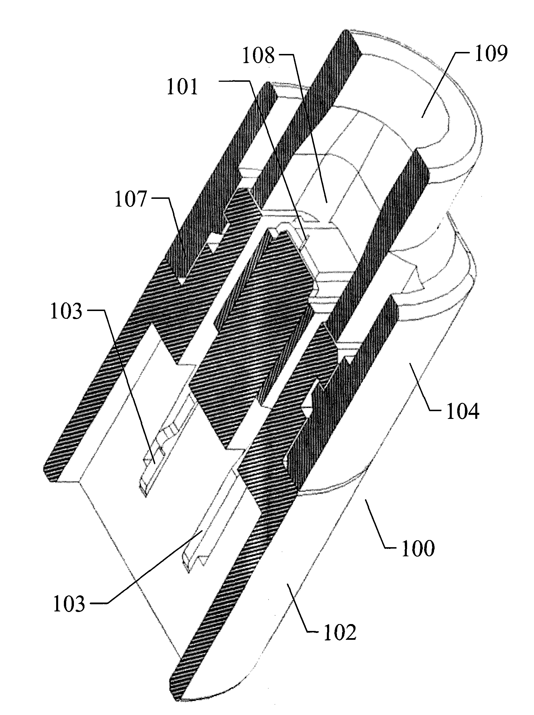
[0033] The ignition charge production method of the present invention is based on the ignition head technical solution disclosed in the patent application document 200910078238.5, such as figure 1 The schematic cross-section is shown. The ignition head 100 includes an ignition bridge wire 101 , a pair of metal sheets 103 , a metal sheet base 102 , and a chamber shell 104 . Wherein, the cavity housing 104 is composed of an assembly cavity 107 , a drug cavity 108 , and an ignition cavity 109 , and the ignition bridge wire 101 welded on a pair of metal sheets 103 is assembled into the drug cavity 108 through the assembly cavity 107 . The sectional view of ignition head 100 after assembly is as follows figure 1 shown.

[0034] The present invention is further designed on the basis of the structure of the above...


PUM


Abstract

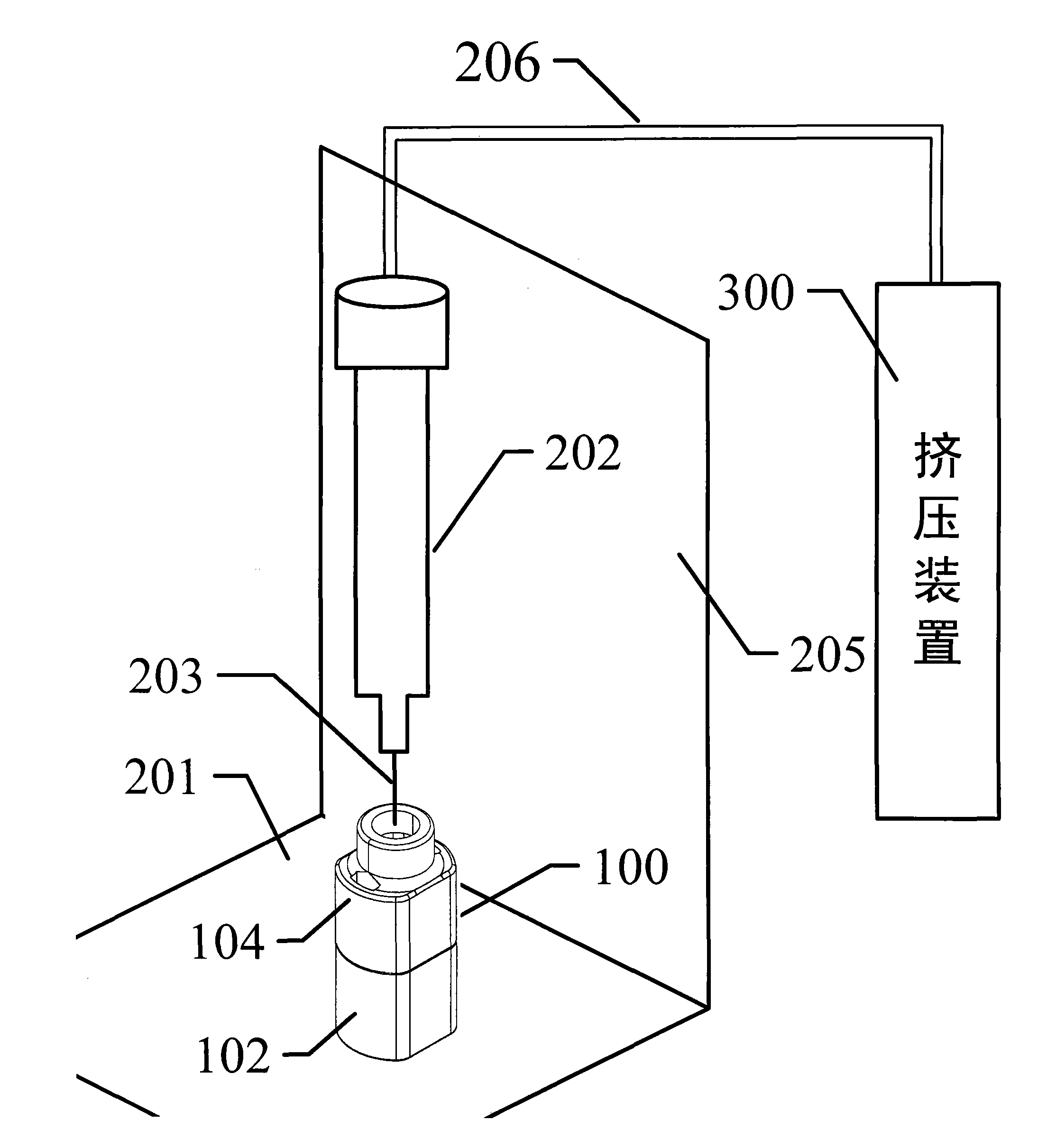
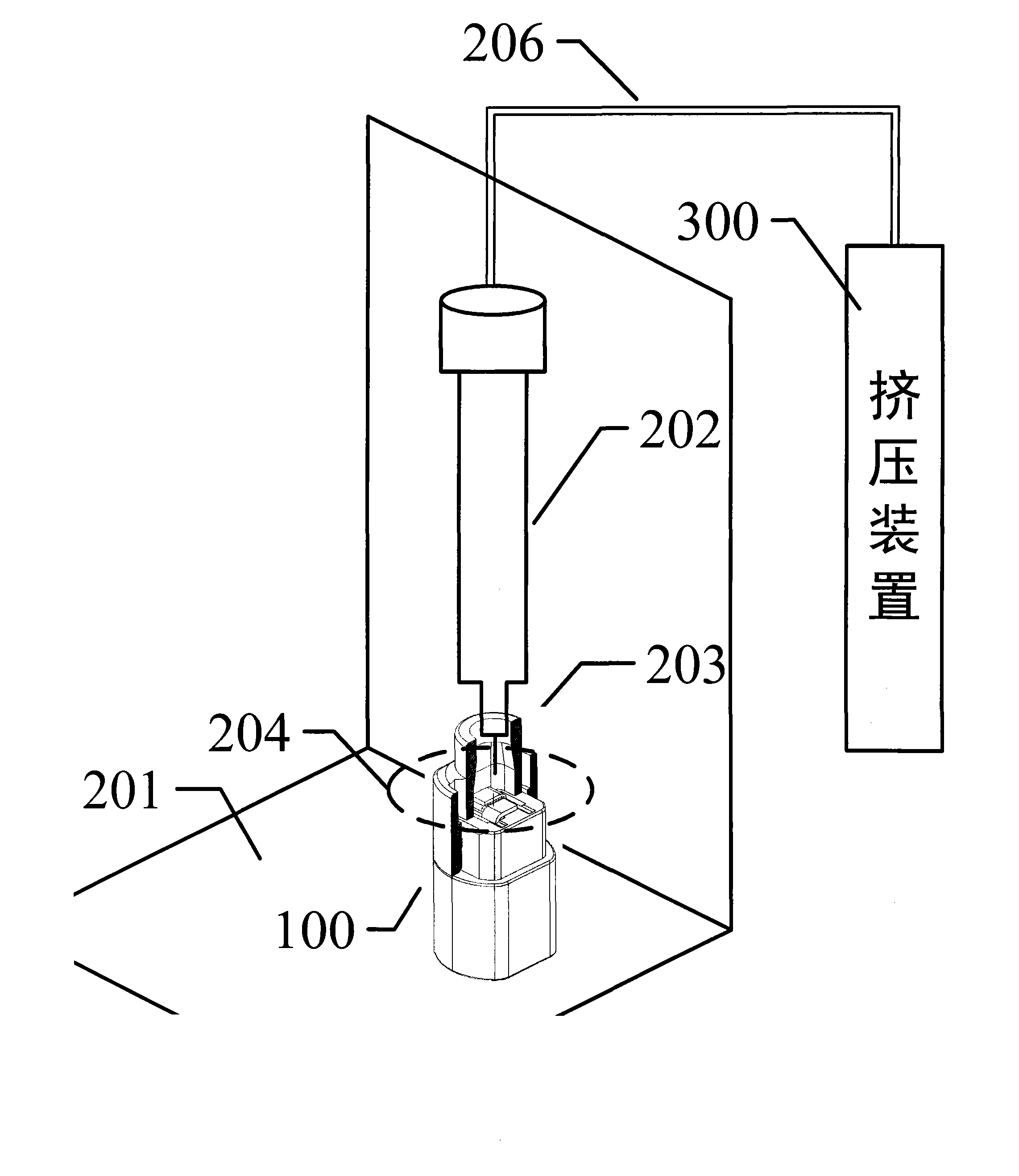
The invention provides a method for producing a detonator explosive ignition head. The method comprises the following processes of: 1, upwards fixedly placing an ignition head explosive cavity on an operating table; 2, adjusting an explosive injection cartridge or the operating table so that the cartridge is positioned right above a cavity shell and aims at an ignition bridge wire; 3, adjusting an explosive injection head or the operating table so that the explosive injection head descends to the explosive cavity; and 4, starting an extrusion device to extrude an ignition agent, and injecting the agent into the explosive cavity so that the agent fully wraps the ignition bridge wire; and finally, extracting the explosive injection head to complete the production. The invention also provides an explosive ignition device for implementing the method, which comprises the operating table, the explosive injection cartridge, the explosive injection head, the extrusion device and an explosion-proof device for isolating a person and the operating table. A fixer on the operating table fixes the ignition head on the operating table, the extrusion device can hermetically connected with the explosive injection cartridge through an air pipe, and the explosive injection cartridge is hermetically connected with the explosive injection head. According to the technical scheme, automatic production of the explosive ignition head can be realized.

Description

technical field [0001] The invention relates to the technical field of pyrotechnics manufacture, in particular to a method for producing an ignition powder head by a dispensing process and a special dispensing device for realizing the method. Background technique [0002] Existing ignition powder manufacturing, mostly adopts dipping technology. The dipping tip is a key process in the manufacture of the electric ignition tip. The specific dipping method depends on the structure and process of the ignition head. There are single-shot manual dipping, multiple-shot manual dipping and automatic dipping, etc. Single-shot manual dipping is to use artificial methods to dip the hair one by one. Multi-fat manual dipping is to clamp and dip multiple semi-finished electric ignition heads, and transfer them with a conveyor belt for assembly-line operation. Automatic dipping is a manufacturing method that uses a rigid structure drug head. Put the drug head on the drug dipping machine a...

Claims


Application Information

Patent Timeline
Patent Type & Authority Applications(China)
IPC IPC(8): F42C19/12
Inventor 颜景龙
Owner BEIJING BANGIUNION TECH DEV
Learn More