
Device and method for testing superconductivity of three-dimensional low-temperature superconducting thin film coil

A technology of low-temperature superconducting and thin-film coils, which is applied in the measurement of magnetic properties, etc., and can solve the problem of insufficient experimental data

Inactive Publication Date: 2011-06-15
HARBIN INST OF TECH
View PDF3 Cites 16 Cited by
  • Summary
  • Abstract
  • Description
  • Claims
  • Application Information

AI Technical Summary

Problems solved by technology

[0003] The phenomenon of superconductivity has attracted the attention of the physics community since its discovery. Einstein was also very interested in superconductivity before 1915. However, due to the lack of experimental data, Einstein did not continue to study low-temperature superconductivity.

Method used


Image

  • Device and method for testing superconductivity of three-dimensional low-temperature superconducting thin film coil
  • Device and method for testing superconductivity of three-dimensional low-temperature superconducting thin film coil
  • Device and method for testing superconductivity of three-dimensional low-temperature superconducting thin film coil

Examples


specific Embodiment approach 1

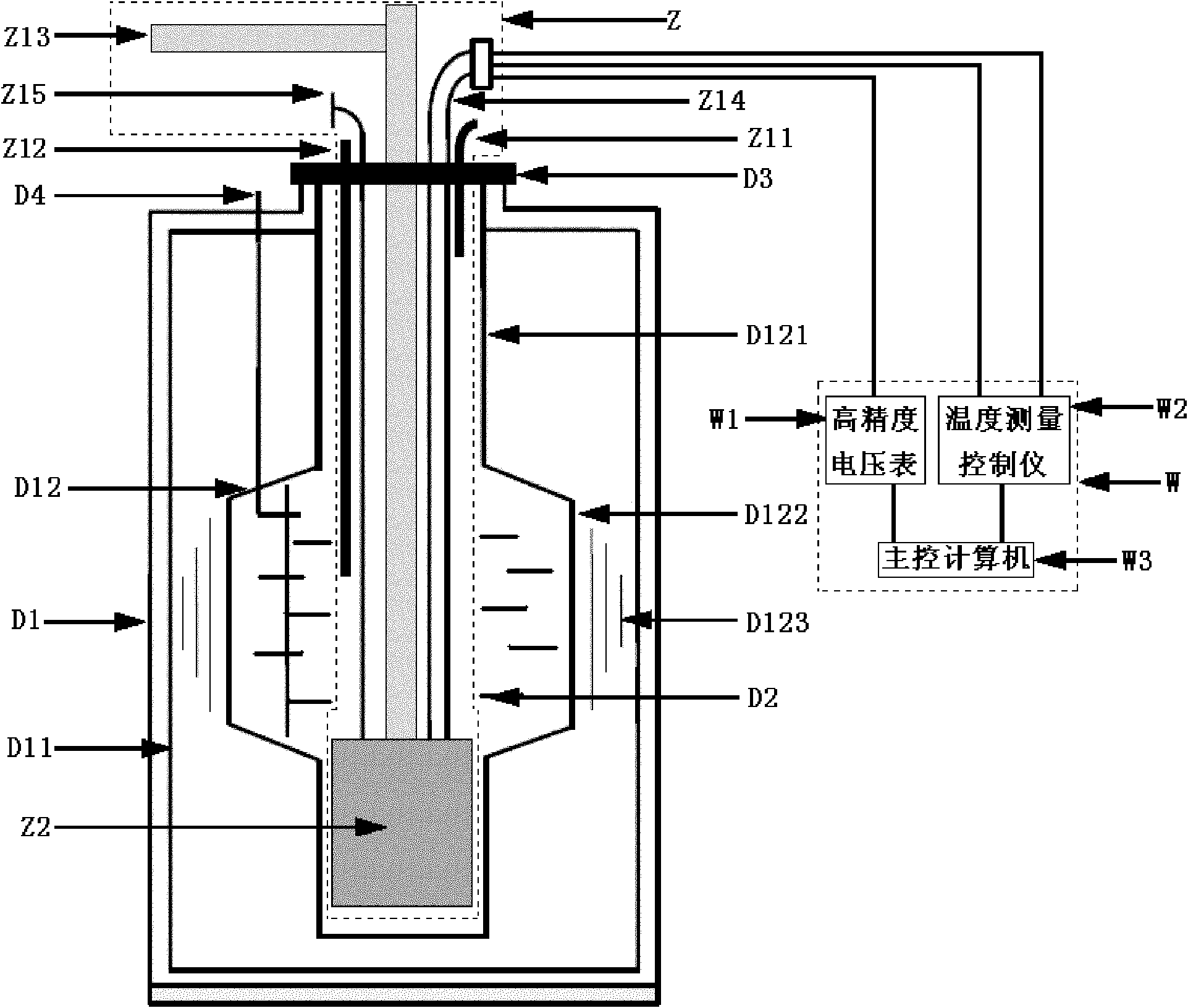
[0034] Specific implementation mode one: combine figure 1 , figure 2 , image 3 and Figure 4 Describe this embodiment, this embodiment includes low temperature environment system D, vacuum environment system Z, test work system C and external measurement control system W;

[0035] The external measurement control system W includes a high-precision voltmeter W1, a temperature measurement control instrument W2 and a main control computer W3;

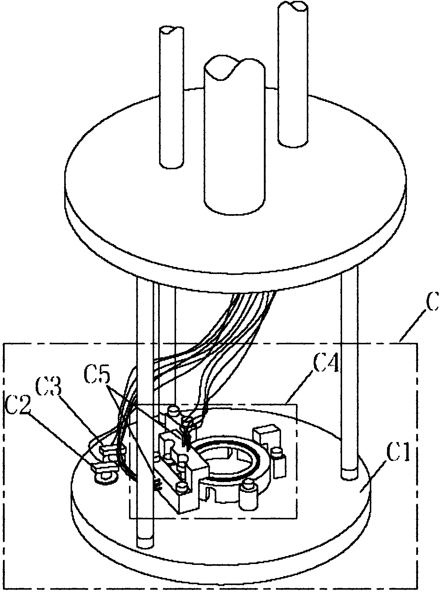
[0036] The test working system C includes a test disc-shaped copper plate C1, a thermometer C2, a heater C3, a clamping coil assembly C4 and at least one compression spring probe C5;

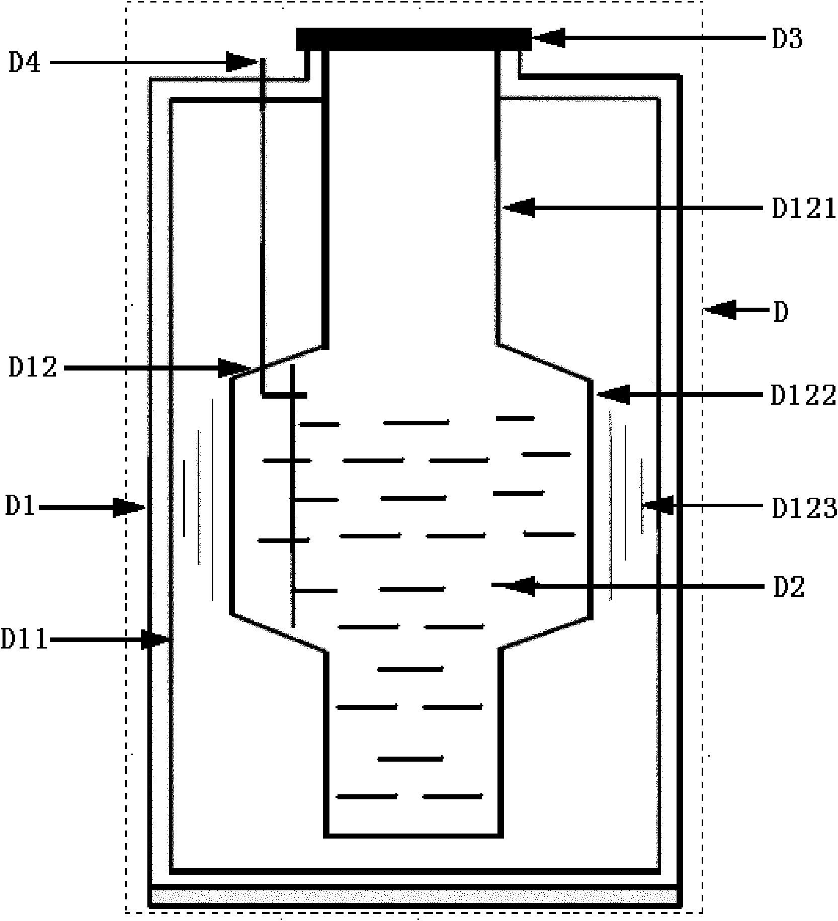
[0037] Low temperature environment system D includes Dewar bottle D1, liquid helium D2 and Dewar bottle cap D3;

[0038] The vacuum environment system Z includes a vacuum tank Z2 and five metal pipes,

[0039] The five metal pipes are the exhaust pipe Z11, the coolant injection pipe Z12, the vacuum pump pipe Z13, the first electrical interface sealing...

specific Embodiment approach 2

[0051] Specific implementation mode two: combination figure 1 and figure 2 Describe this embodiment, the difference between this embodiment and the specific embodiment is that the Dewar bottle D1 has an inner and outer two-layer shell structure, the outer shell D11 is a cylindrical metal tank with an open upper end, and the inner shell D12 is a three-section cylindrical inner shell. The connection forms the tank body, and the cavity between the inner and outer shells is a vacuum. The main purpose is to make the low temperature environment inside the Dewar D1 well insulated from the room temperature environment outside.

[0052] The three-section cylindrical inner shells are successively the upper cylindrical inner shell D121, the middle cylindrical inner shell D122 and the lower cylindrical inner shell D123 from top to bottom, and the three-section cylindrical inner shells hold the liquid in the Dewar bottle D1 The helium space is divided into a low heat conduction pipe neck...

specific Embodiment approach 3

[0059] Specific implementation mode three: combination image 3 and Figure 4 Describe this embodiment. The first difference between this embodiment and the specific embodiment is that the clamping coil assembly C4 includes a plane positioning block C41, a cylindrical positioning pin C42 and a clip C43 with a spring piece, wherein the plane positioning block C41 is located on the measured The upper part of one side of the three-dimensional low-temperature superconducting thin-film coil is provided with a boss, which is used to block the upward transmission displacement of the measured three-dimensional low-temperature superconducting thin-film coil due to vibration, which is made of G10 material; the cylindrical positioning pin C42 and the The clip C43 of the spring sheet is made of copper, and the plane positioning block C41, the cylindrical positioning pin C42 and the clip C43 with the spring sheet are respectively fixed on the test disc-shaped copper plate C1, and distribut...


PUM

PropertyMeasurementUnit
Resistanceaaaaaaaaaa

Abstract

The invention relates to a device and method for testing the superconductivity of a three-dimensional low-temperature superconducting thin film coil, belonging to the field of a low-temperature superconductivity technology and high-accuracy measurement. Particularly, the superconductivity test is carried out on the three-dimensional low-temperature superconducting thin film coil, the superconductivity of the three-dimensional low-temperature superconducting thin film coil is tested and researched by means of a vacuum and low-temperature environment provided by a low-temperature environmental system and a vacuum environmental system provided by the invention, and further the three-dimensional superconducting thin film coil is designed in an auxiliary manner. The invention designs a low-temperature system for testing the superconductivity of the three-dimensional low-temperature superconducting thin film coil, therefore, a low-temperature environment needs to be provided for superconducting coils, as described in the background technology, in the low-temperature environment provided by the invention, liquid helium is utilized as a refrigerant, and the working temperature of a testing system is ensure to reach 4.2K, namely minus 269 DEG C. Therefore, as the tested three-dimensional low-temperature superconducting thin film coil is a core part in payloads of an STEP (satellite test of the equivalence principle) jointly developed by the NASA (National Aeronautics and Space Administration) and the ESA (European Space Agency), the device and method provided by the invention belong to applied aerospace science and technology in terms of technology application.

Description

technical field [0001] The invention belongs to the field of low-temperature superconducting technology and high-precision measurement, and specifically relates to a technology for measuring and testing superconducting characteristics of a three-dimensional low-temperature superconducting film coil in an aerospace device by using the system. Background technique [0002] Cryogenic technology began with the liquefaction of helium in 1908 by Dutch physicist Heike Kamerlingh-Onnes. Helium is the substance with the lowest boiling point, that is, it can only be liquefied at 4.2K (-269°C). Onnes used liquid helium to create a temperature environment below 10K, and began to study the conductivity of metals in such a low temperature environment. Unexpectedly, Onnis discovered in 1911 that the resistance of mercury metal suddenly dropped to zero resistance when the temperature dropped to 4.2K, and then after many tests, he found that even with a little impurity, the resistance of me...

Claims


Application Information

Patent Timeline
IPC IPC(8): G01R33/12
Inventor 曹喜滨杨勇王肃文张锦绣张世杰兰盛昌李梦立
Owner HARBIN INST OF TECH
Learn More