Electromagnetic induction coil panel and manufacturing process thereof

An electromagnetic induction coil and manufacturing process technology, applied in coil manufacturing, coil device, induction heating, etc., can solve problems such as potential safety hazards, deformation of coil windings and magnetic strips, complex dispensing process, etc., and achieve cleanliness and sanitation. The effect of production process and firm structure

Active Publication Date: 2011-06-15
MIDEA GRP CO LTD
0 Cites 12 Cited by

AI-Extracted Technical Summary

Problems solved by technology

However, under the influence of factors such as transportation and high temperature, the coil coil with the above structure is prone to deformation and falling off of the coil winding an...

Abstract

The invention discloses an electromagnetic induction coil panel, which comprises a coil winding, a plastic bracket and a plurality of magnetic stripes, wherein the coil winding is wound in a wire casing on the upper surface of the plastic bracket; the plurality of magnetic stripes are arranged in a plurality of accommodation grooves formed on the lower surface of the plastic bracket respectively; and one or more positioning lug bosses are arranged on the two sides of each of the wire casing and the accommodation grooves, and are hot-pressed to embed the coil winding into the wire casing and partially wrap the magnetic stripes. The manufacturing process comprises the following steps of: 1, winding the coil winding in the wire casing on the upper surface of the plastic bracket; 2, clamping the magnetic stripes in the accommodation grooves on the lower surface of the plastic bracket; and 3, simultaneously heating the two surfaces of the plastic bracket to heat, soften and deform the positioning lug bosses on the two sides of each of the wire casing and the accommodation grooves, and pressing the lug bosses to embed the coil winding into the wire casing and integrate the coil winding and the wire casing and partially wrap the magnetic stripes. According to the manufacturing process, a process flow is simplified and working environment is clean and sanitary; and the coil panel has a secure and stable structure.

Application Domain

Technology Topic

Image

  • Electromagnetic induction coil panel and manufacturing process thereof
  • Electromagnetic induction coil panel and manufacturing process thereof
  • Electromagnetic induction coil panel and manufacturing process thereof

Examples

  • Experimental program(1)

Example Embodiment

[0021] Specific implementation plan
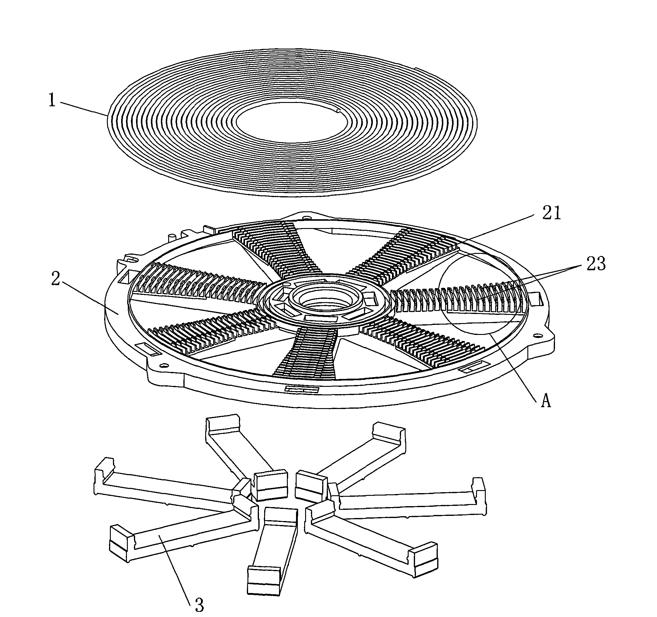
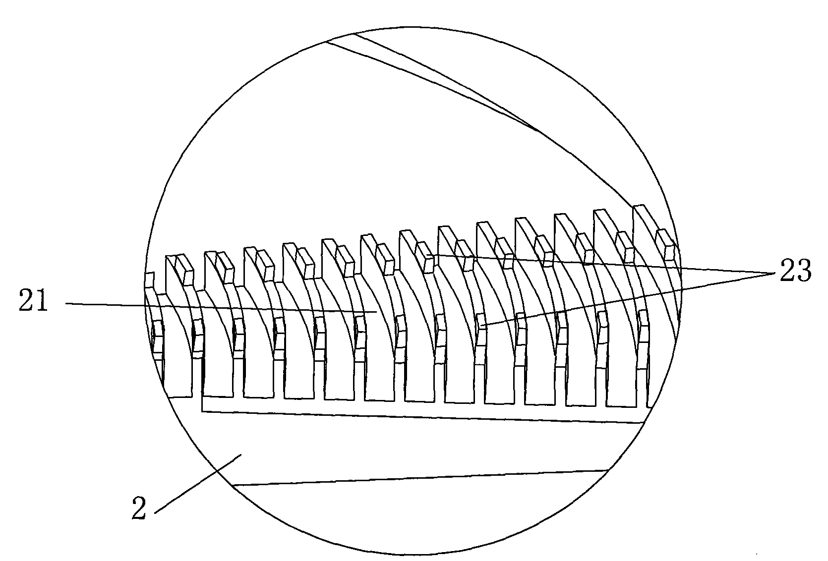
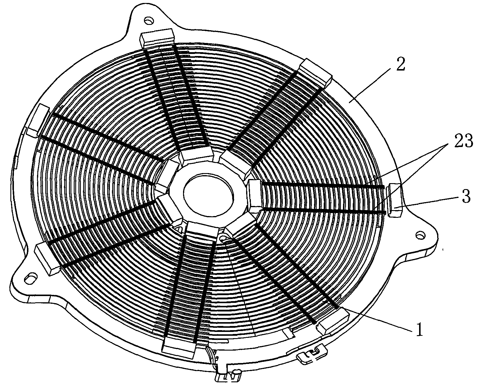
[0022] The structure diagram of the electromagnetic induction coil disk of the present invention is as figure 1 , 2 , 3, 4, 5, 6, including a coil winding 1, a plastic support 2 and a number of magnetic strips 3. The coil winding 1 is wound in the slot 21 on the upper surface of the plastic support, and the magnetic strips 3 are respectively mounted on the plastic In a number of accommodating grooves 22 provided on the lower surface of the support 2, one or more positioning bosses 23 are respectively provided on both sides of the wire groove 21 and the accommodating groove 22, and the positioning bosses 23 are hot-pressed to embed the coil winding 1 It enters into the wire groove 21 and is integrated with the wire groove, and the positioning boss 23 is hot pressed to partially wrap the magnetic strip 3. In this embodiment, there are 7 accommodating grooves 22, and 7 corresponding to the magnetic strip 3, and two positioning bosses 23 are respectively provided on both ends of the wire groove 21 and the accommodating groove 22.
[0023] In order to make the positioning boss 23 hot press, the coil winding 1 is embedded in the wire slot 21, so that the positioning boss partly wraps the magnetic strip 3, the depth of the wire slot on the plastic bracket is 0.5 higher than the wire diameter of the coil winding ~2.5mm, the height of the above positioning boss is 0.5~2.5mm.
[0024] The manufacturing process of the electromagnetic induction coil disk of the present invention includes the following steps:
[0025] (1) Winding the coil winding 1 in the slot 21 on the upper surface of the plastic support 2 to complete the preliminary fixing of the coil winding;
[0026] (2) The seven magnetic strips 3 are respectively clamped into the accommodating slots 22 on the lower surface of the plastic bracket 2 to complete the preliminary fixing of the magnetic strips;
[0027] (3) Both sides of the plastic bracket 2 are heated at the same time through the hot pressing plate, so that the positioning bosses 23 on both sides of the upper surface of the plastic bracket and the lower surface of the accommodating groove are heated and softened and deformed, and the positioning bosses are pressed to make the coil winding 1 It is embedded in the wire groove 21 and integrated with the wire groove, and the positioning boss is press-fitted to partially wrap the magnetic strip 3.
[0028] The above-mentioned hot pressing plate realizes the control of pressure, temperature, and pressing time in the pressing process of the hot pressing plate through common circuit control elements such as a cylinder, a temperature controller, and a time relay. The control range is pressure from 30 to 200N, temperature from 180 to 260°C, and time from 5 to 30 seconds.
[0029] After the above process, the coil winding and the magnetic strip are firmly fixed in the plastic bracket.

PUM

PropertyMeasurementUnit
Height0.5 ~ 2.5mm
tensileMPa
Particle sizePa
strength10

Description & Claims & Application Information

We can also present the details of the Description, Claims and Application information to help users get a comprehensive understanding of the technical details of the patent, such as background art, summary of invention, brief description of drawings, description of embodiments, and other original content. On the other hand, users can also determine the specific scope of protection of the technology through the list of claims; as well as understand the changes in the life cycle of the technology with the presentation of the patent timeline. Login to view more.

Similar technology patents

Multifunctional integrated tissue embedding box

InactiveCN109443897ASimplify the production processReduce chance of confusionPreparing sample for investigationTissue EmbeddingFastener
Owner:沈阳安真医疗器械有限公司

Classification and recommendation of technical efficacy words

  • Keep clean
  • Simplify the production process

Electronic device and operation method thereof

InactiveCN104423433AKeep cleanProtect electronic equipmentDetails for portable computersEmbedded systemSolid-state
Owner:LENOVO (BEIJING) CO LTD

Portable saline nasal spray

InactiveUS20080081079A1Keep cleanBiocideSpray nozzlesSpray nozzleSaline nasal
Owner:CHA BYUNG KWON

Hot-rolled pickled plate and production method thereof

Owner:ZHANGJIAGANG YANGTZE RIVER COLD ROLLED PLATE CO LTD

Production method of dipotassium phosphate

InactiveCN104003362ASimplify the production processReduce energy and water consumptionPhosphorus compoundsPotassium hydroxideHeavy metals
Owner:GUIYANG KAILIN FERTILIZER CO LTD +1
Why Eureka
Try Eureka