Wire sawing device

A technology of wire sawing and sawing, which is applied in the field of wire saws, can solve the problems of scrapped workpieces, and achieve the effects of saving space, reducing costs, reducing investment costs and operating costs

Inactive Publication Date: 2011-06-15
SCHOTT SOLAR AG (DE)
View PDF5 Cites 1 Cited by
  • Summary
  • Abstract
  • Description
  • Claims
  • Application Information

AI Technical Summary

Problems solved by technology

If such a fine sawing wire is now broken, the entire sawing process must be stopped and the corresponding workpiece must be voided over its entire length or part of its length

Method used


Image

  • Wire sawing device
  • Wire sawing device
  • Wire sawing device

Examples


Embodiment Construction

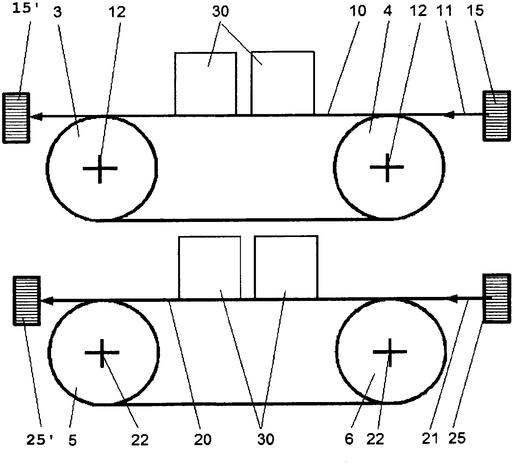
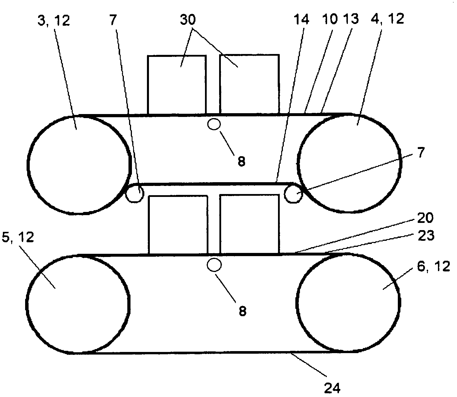
[0019] Such as figure 1 with 2 As shown, the sawing device according to the first embodiment includes a first sawing zone 10 and a second sawing zone 20, which respectively surround a pair of wire guide rollers 3, 4, and 5 as wire guide mechanisms. 6 stretched into. The drum has grooves, which determine the sawing pitch. The wire guide mechanism or the axis of the drum is arranged in parallel and, for example, is assembled in a machine frame not shown. Of course, the device can also have more than four wire guide rollers. The wire guide rollers 3, 4, 5, 6 define the parallel planes of the sawing areas 10, 20 through their upper envelope. By figure 1 The wire storage 15 or 15', 25 or 25' shown in the provide separate sawing wires 11, 21, where the wire storage here is composed of an unwinding coil and a winding coil, respectively, and the movement of the wire is indicated by arrows direction. Of course, the direction of line movement can be reversed.

[0020] The wire drives ...


PUM

PropertyMeasurementUnit
diameteraaaaaaaaaa

Abstract

The invention describes a wire saw which, in order to saw at least one workpiece (30), has one or more saw wires that are clamped between wire guiding means (3, 4, 5, 6) and form a field of saw wires arranged equidistantly next to one another. The wire saw comprises at least two saw fields (10, 20), each saw field having an independent wire drive (12, 22). The saw fields are preferably arranged one above another. Each saw field (10, 20) usually has an independent wire accumulator (15, 20) which can be used to continuously feed respectively separate saw wires (11, 21).

Description

Technical field [0001] The invention relates to a wire saw as described in the preamble of the independent claim. Background technique [0002] This type of wire saw device for moving the wire or the workpiece to be sawed is known, especially in the electronic component industry made of pure iron, quartz, and silicon oxide, for obtaining thin slices, so-called wafers, and more. Crystal or single crystal silicon materials or GaAs, InP, GGG and other materials or quartz, artificial sapphire materials and ceramic materials. [0003] In the known device, a sawing area or a sawing field is formed by adjacent wires, for example, the wires are stretched by a set of at least two rollers arranged in parallel. The drum here has grooves, which determine the distance between the sawing zone lines and therefore also the thickness of the slice to be sawed. In this way they also act as thread guides. The workpiece itself to be sawed is, for example, fixed on a platform that moves perpendicular...

Claims


Application Information

Patent Timeline
Patent Type & Authority Applications(China)
IPC IPC(8): B23D57/00
CPCB23D57/0023B23D57/0061
Inventor A·门策尔
Owner SCHOTT SOLAR AG (DE)
Why Eureka
Try Eureka