
Retractable/extendable crank using a cylindrical cam, an end cam, or a swash plate cam, and bicycle using the same

一种圆柱凸轮、端面凸轮的技术,应用在机械零件领域,能够解决曲柄旋转机构复杂、难以安装自行车、制造费用高等问题,达到结构简单、简单适用、使用方便的效果

Inactive Publication Date: 2011-06-15
李根亨
View PDF8 Cites 5 Cited by
  • Summary
  • Abstract
  • Description
  • Claims
  • Application Information

AI Technical Summary

Problems solved by technology

The variable-length crank rotation mechanism disclosed in this patent is not only complicated, but also has a large number of components, so the manufacturing cost is very high, and it is difficult to install on existing bicycles
[0009] In addition, a bicycle with a transmission that obtains a larger torque uses multiple gears, so that it is easy to climb a hill; at this time, although the torque is increased, it is easy to climb a hill, but in order to obtain a larger torque, it must be changed to a low speed, so speed will inevitably decrease

Method used


Image

  • Retractable/extendable crank using a cylindrical cam, an end cam, or a swash plate cam, and bicycle using the same
  • Retractable/extendable crank using a cylindrical cam, an end cam, or a swash plate cam, and bicycle using the same
  • Retractable/extendable crank using a cylindrical cam, an end cam, or a swash plate cam, and bicycle using the same

Examples


Embodiment 1

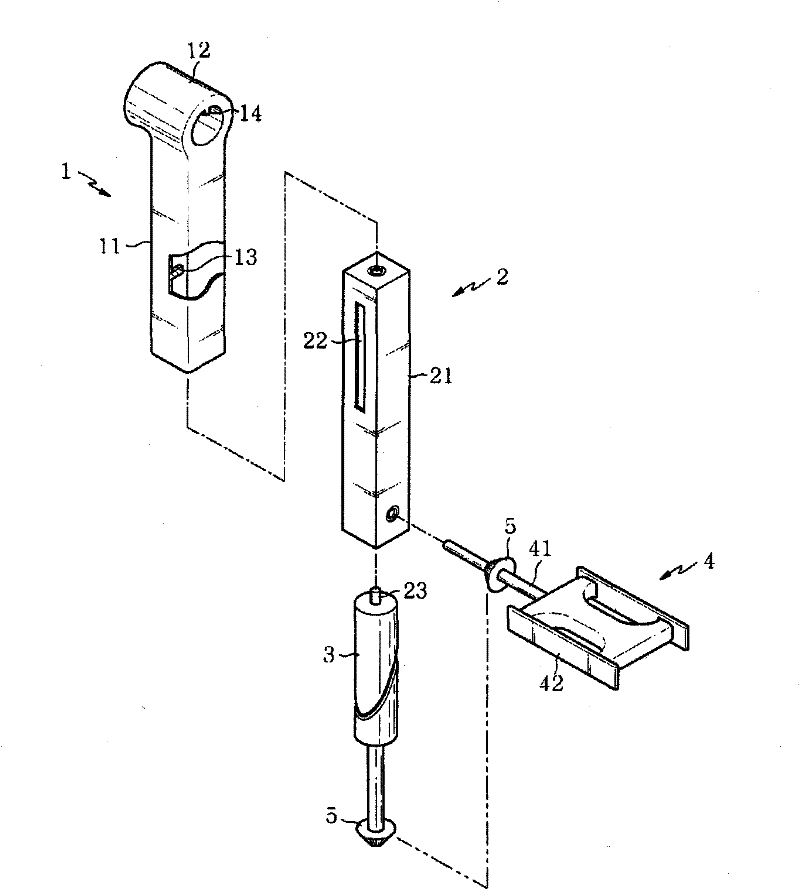
[0027] Utilize the retractable crank of cylindrical cam of the present invention, as figure 1 As shown, it includes: a crank, which is composed of a fixed arm 1 and a movable arm 2; the fixed arm 1 is connected to the rotating shaft of the rotating body; the movable arm slides inside the fixed arm 1; The inside of the arm 2 rotates; a pedal 4 , which is connected to the exposed end of the movable arm 2 ;

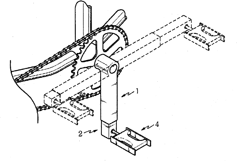
[0028] figure 2 is a diagram for driving a bicycle with a telescoping crank using a cylindrical cam with the above structure according to the present invention.

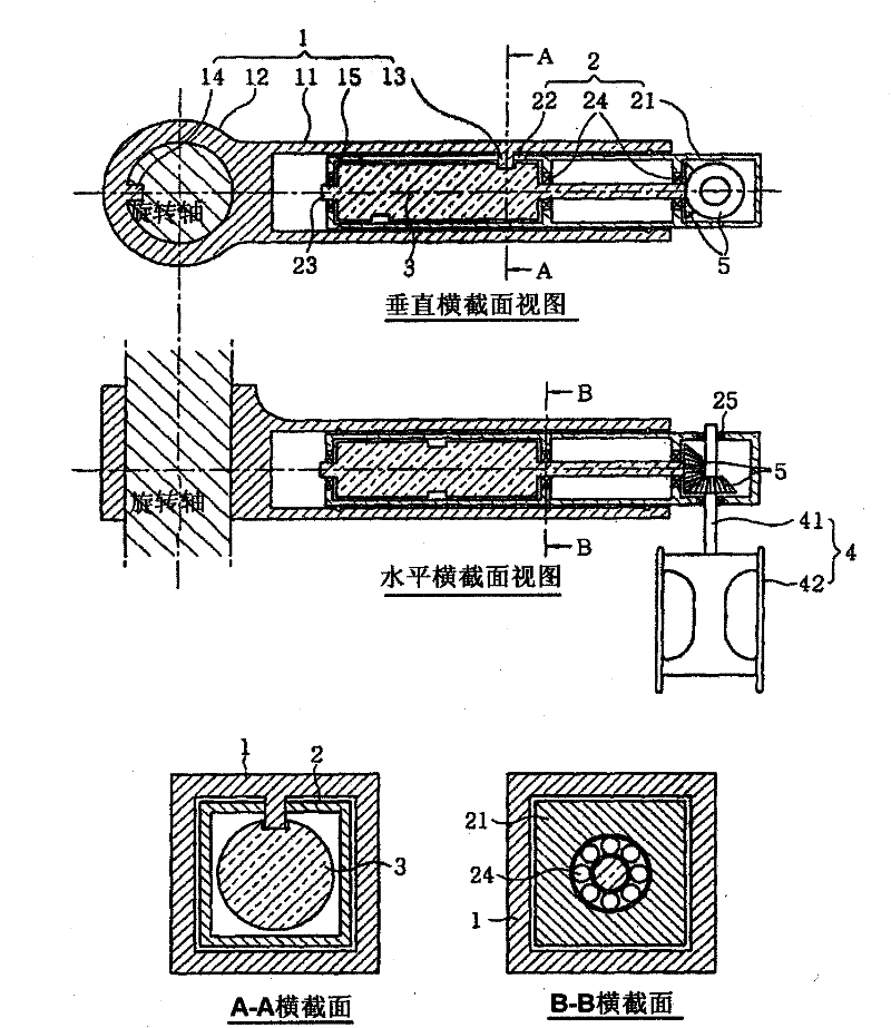
[0029] Such as image 3 As shown, the fixed arm 1 has a fixed arm body 11; one end of the fixed arm body 11 is formed with a hub 12, the hub 12 is coupled with the rotating shaft, and the other end of the fixed arm body 11 forms an opening to insert the movable arm 2-1 and make the The movable arm 2 expands and contracts. The cam guide 13 protrudes inwardly from the side of the fixed arm body 11 . The hub 12 ...

Embodiment 2

[0048] The retractable crank can also use end face cam 3-1 or swash plate cam 3-2 to replace cylindrical cam 3. When using the end face cam or the swash plate cam, there should be a tight spring 6, so that the cam surface and the cam guide 13 of the fixed arm are kept in close contact.

[0049] The shape of the end face cam 3-1 is as Figure 6 (a) shown. The end face cam 3-1 is manufactured by coupling a rotating shaft to a cam body formed by machining one end of a tube or cylinder of predetermined thickness into an inclined surface against which the cam guide 13 is snugly attached. When the end cam 3-1 rotates around the cam shaft, the end cam 3-1 reciprocates through the cam guide 13 fixed on the fixed arm, thus, the movable arm of the end cam 3-1 is installed 2 Telescopic movement when reciprocating sliding.

[0050] The shape of the swash plate cam 3-2 is as Figure 6 (b) shown. The swash plate cam 3-2 is manufactured by forming a disk-shaped slant plate inclined on t...

Embodiment 3

[0057] Same as the first embodiment, a cylindrical cam is also used as another embodiment of the present invention, and the crank at this time installs the cylindrical cam inside the fixed arm instead of inside the movable arm.

[0058] Such as Figure 8 As shown, the telescopic crank using a cylindrical cam according to this embodiment includes: a crank consisting of a fixed arm 1-1 and a movable arm 2-1, the fixed arm 1-1 is connected to the rotating shaft of the rotating body, The movable arm 2-1 slides outside the fixed arm 1-1; a cylindrical cam 3-1 rotates inside the fixed arm 1-1; a pedal (not shown in the figure) is connected to the movable arm 2 -1 end; a pair of bevel gears (5), one of which is connected to the shaft of the cylindrical cam 3-1, and the other is connected to the shaft of the pedal.

[0059] The fixed arm 1-1 is the same as that of Embodiment 1, a hub 12-1 connected to the rotating shaft is formed at one end of the fixed arm body 11-1, and the other e...


PUM


Abstract

The present invention relates to a mechanical element, and more particularly, to a crank connected to a bicycle pedal or a handle for rotating a rotary body and to a bicycle using the same. The present invention uses a cylindrical cam, an end cam, or a swash plate cam, and the shafts of these cams and a shaft of a pedal or a handle for applying force are equipped with a miter gear (a bevel gear the number of teeth of which is 1:1 and the shaft angle of which is 90 degrees), such that the crank retracts / extends one time per one rotation of the pedal or the handle. The retractable / extendable crank of the present invention is advantageous in that the length of the crank is elongated to generate a large amount of rotating force in a force-applying section, and shortened in a section where no force is applied to reduce the actuating space occupied by the crank and apply a large amount of torque to the rotary body from the same force, without deviating from the normal motion range of the arms or legs during rotation. The retractable / extendable crank of the present invention has a significantly rigid structure and provides reliable operation, and thus is suitable as a driving crank to beconnected to a pedal of a bicycle. As compared with conventional bicycles, the bicycle using the crank of the present invention is supplied with a larger amount of rotating force in proportion to theelongation of the crank from the same force, thus enabling the bicycle of the present invention to travel quickly with less force and climb a steep upward slope in an easy manner.

Description

technical field [0001] The present invention relates to a mechanical part, and more particularly, to a crank connected to a bicycle pedal or a handle for rotating a rotating body, and a bicycle using the crank. Background technique [0002] One end of the crank that rotates the rotating body is fixed to the shaft of the rotating body, and the other end is connected to a unit that applies force to the handle, pedal, etc. The torque T to turn the rotating body is the value of the length (corresponding to the arm length) L of the crank multiplied by the force applied at the end of the crank. It is expressed in a mathematical formula as follows. [0003] T=F×L, here, F: force, L: arm length [0004] It can be seen from the mathematical formula that when the length of the arm is lengthened, that is, the length of the crank is lengthened, a greater torque can be obtained with the same force. When applied to a bicycle, the bicycle becomes faster and climbs steep grades more easi...

Claims


Application Information

Patent Timeline
Patent Type & Authority Applications(China)
IPC IPC(8): B62M3/02B62M3/04B62M3/06B62M1/02B62M1/36
CPCB62M3/04B62M3/06Y10T74/2165Y10T74/2167B62K19/34B62M1/10B62M3/02
Inventor 李根亨
Owner 李根亨
Learn More