Liquid damping time delayer

A technology of liquid damping and delay device, applied in the direction of liquid shock absorber, shock absorber, shock absorber, etc., can solve the problems of large delay time change, easy blockage of tiny holes, large compressed gas, etc. Reliability and safety, reducing its own volume, reducing the effect of delay effects

Active Publication Date: 2011-06-22
SHANGHAI JINDUN FIRE FIGHTING SECURITY TECHCO
View PDF5 Cites 8 Cited by
  • Summary
  • Abstract
  • Description
  • Claims
  • Application Information

AI Technical Summary

Problems solved by technology

When the temperature changes, the delay time changes greatly; the volume of the container itself occupies a large compressed gas (about 1 / 4), which affects the overall control gas pressure; during use, the tiny holes are easier to block; affect the control System reliability and safety performance

Method used


Image

  • Liquid damping time delayer
  • Liquid damping time delayer
  • Liquid damping time delayer

Examples


Embodiment Construction

[0023] The present invention will be further described below in combination with preferred implementation methods with reference to the accompanying drawings.

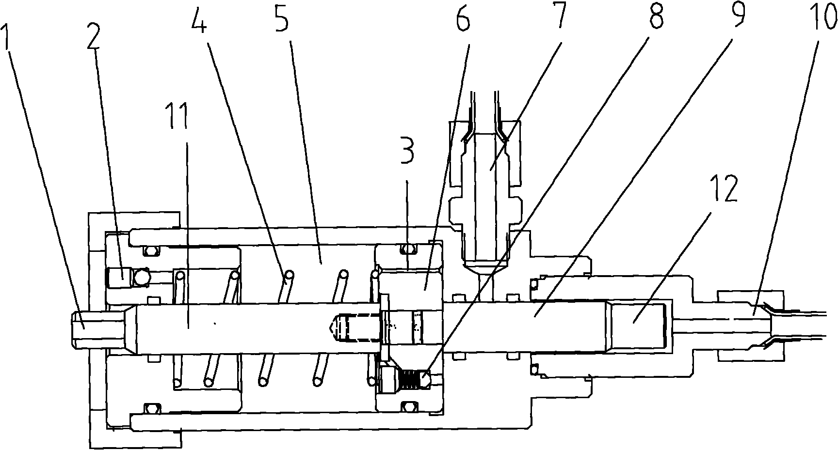
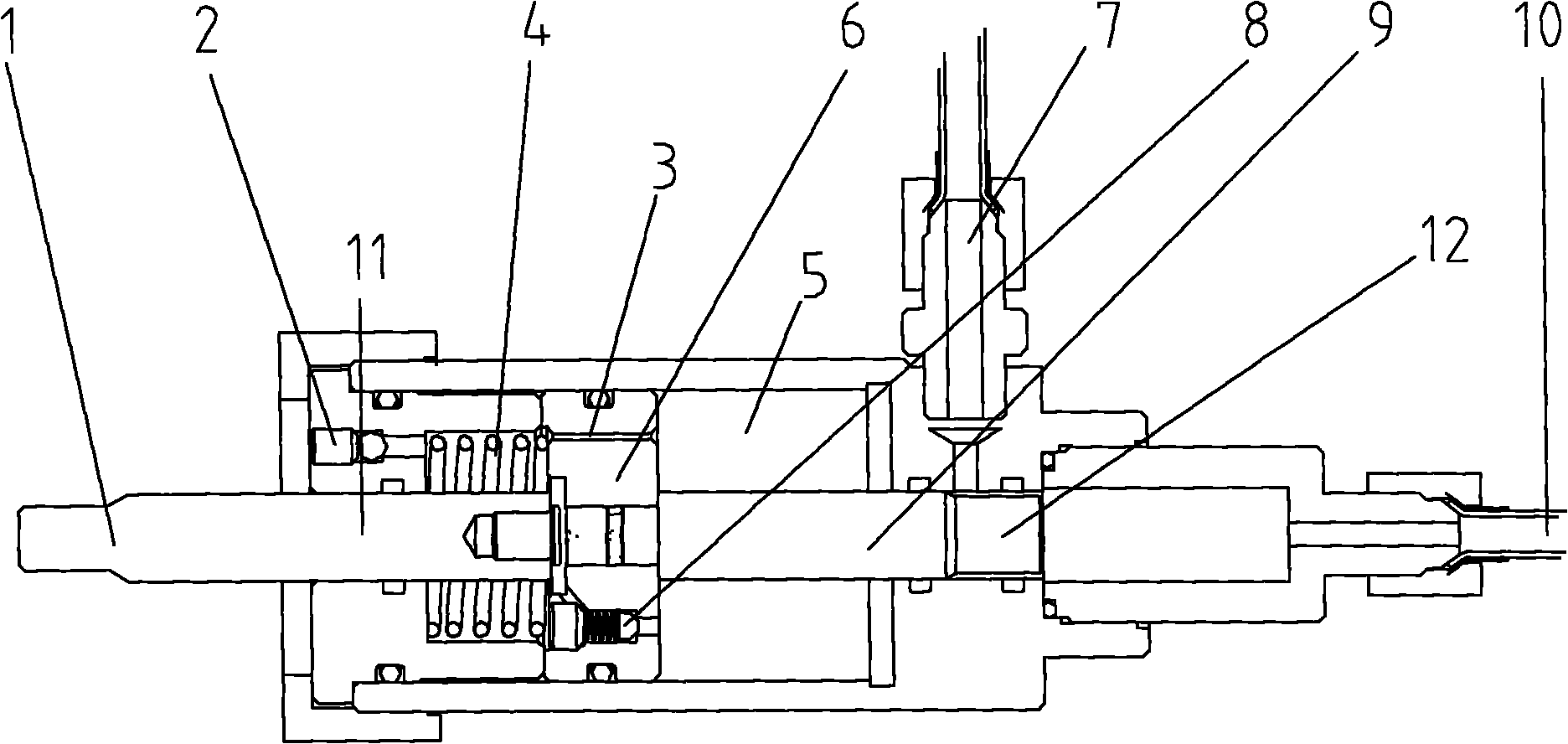
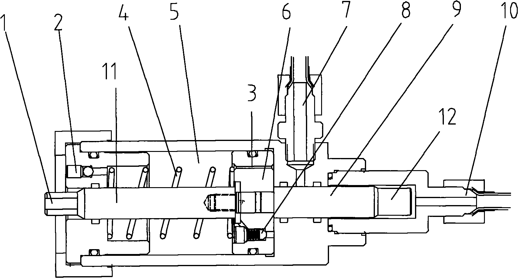
[0024] The invention relates to a liquid damping delayer. including such as figure 1 and figure 2 The gas exchange device and damping device shown. The gas exchange means and the damping means are interconnected.

[0025] The gas exchange device includes an air inlet port 10 , a small piston 9 , a piston reducing end 12 and an air outlet port 7 . The small piston 9 and the piston variable diameter end 12 are located inside the gas exchange device, and the small piston 9 and the piston variable diameter end 12 are connected to each other; the small piston 9 is connected to the inner wall of the gas exchange device Complete fit; the diameter of the reduced diameter end 12 of the piston is smaller than the diameter of the small piston 9; the air inlet port 10 and the air outlet port 7 are orthogonally distributed.

...


PUM


Abstract

The invention provides a liquid damping time delayer for a fire protection safety control system. The liquid damping time delayer comprises a gas exchange device and a damping device which are connected mutually, wherein the gas exchange device comprises a gas inlet interface, a gas outlet interface, a small piston and a piston reduction end, wherein the gas inlet interface and the gas outlet interface are arranged at two ends of the gas exchange device and are communicated with the cavity of the gas exchange device; the small piston and the piston reduction end are arranged in the cavity of the gas exchange device and are connected mutually; the damping device comprises liquid, a liquid adding port, a large damping piston, a guide column, a display rod and a return spring, wherein the liquid fills in the cavity of the damping device; the liquid adding port is communicated with the cavity of the damping device; the large damping piston, the guide column and the display rod are positioned in the cavity of the damping device and are connected mutually; and the return spring is positioned at the circumference of a guiding column. By utilizing the liquid damping time delayer disclosed by the invention, the influence on time delay by the temperature can be reduced, the volume of a container can be reduced, and more reliability and safety can be improved.

Description

technical field [0001] The invention relates to a delay device, in particular to a liquid damping delay device used in a fire safety control system. Background technique [0002] The delayer is a tank container. Installed between the alarm valve and the hydraulic alarm bell (or pressure switch), it is used to prevent false alarms caused by the opening of the alarm valve due to fluctuations in water pressure. After the alarm valve is opened, it takes about 30 seconds for the water flow to fill the retarder before it can hit the hydraulic alarm bell. In the existing fire safety control system, the long-time delayer (about 30 seconds) generally adopts the time when compressed gas is filled into a certain amount of container through tiny holes, or the release time of compressed gas filled into a certain amount of container is used. Time to reach the delay function. When the temperature changes, the delay time changes greatly; the volume of the container itself occupies a larg...

Claims


Application Information

Patent Timeline
Patent Type & Authority Applications(China)
IPC IPC(8): F16F9/16F16F9/34F16F9/36
Inventor 严明华
Owner SHANGHAI JINDUN FIRE FIGHTING SECURITY TECHCO
Why Eureka
Try Eureka