
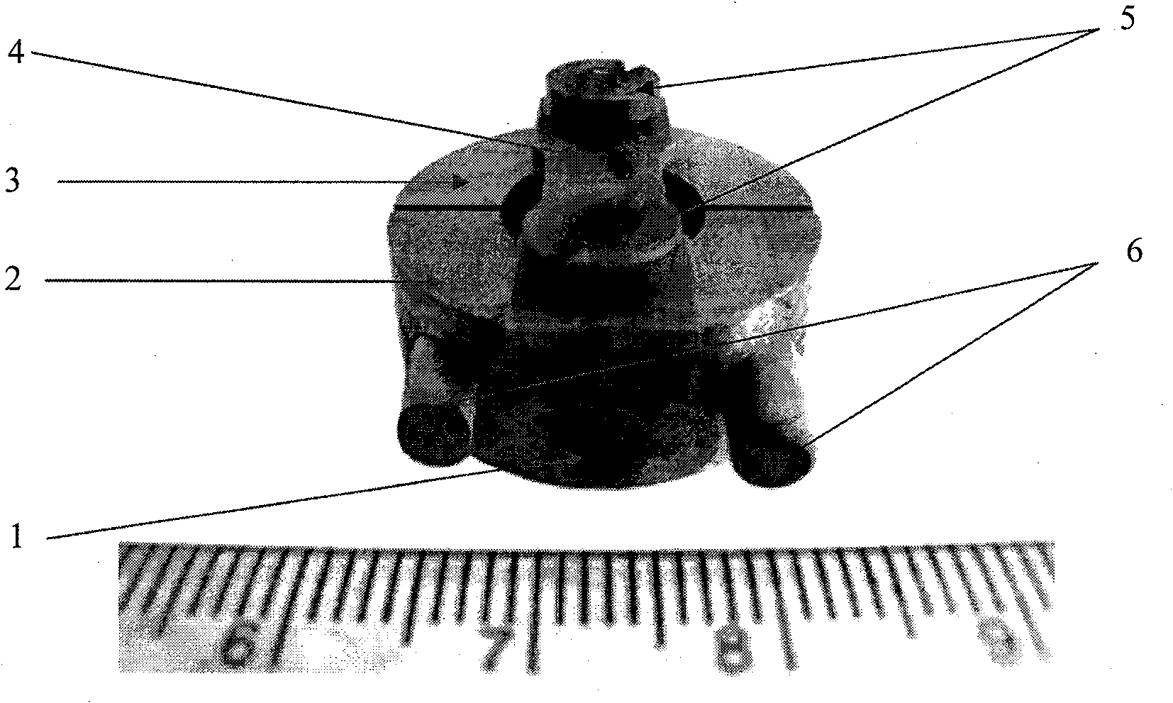
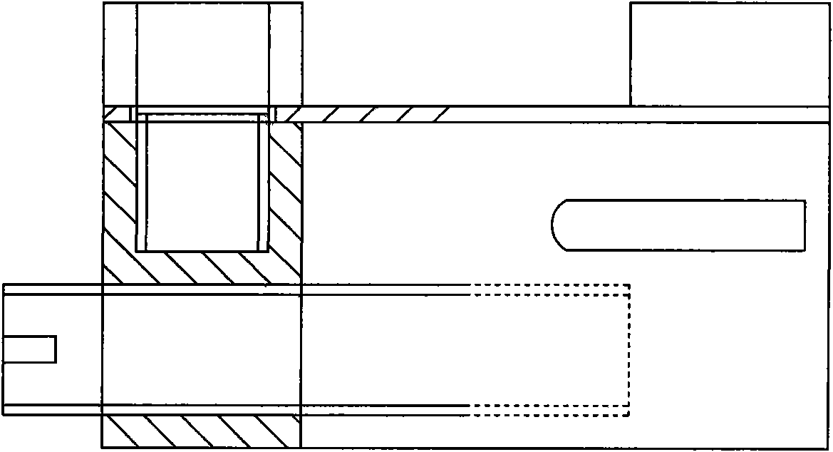
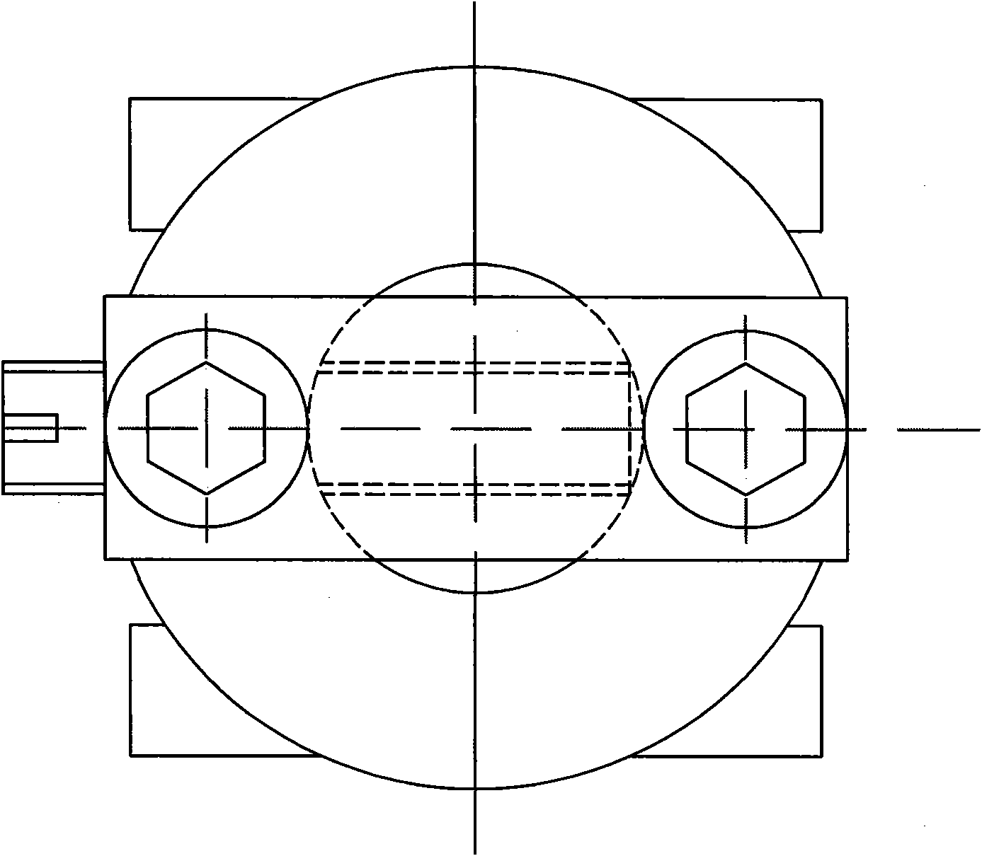
Sample table for scanning electron microscope in-situ observation of stress corrosion cracking of metal material

A stress corrosion, metal material technology used in the field of scanning electron microscope sample stages to solve problems such as limitations

Inactive Publication Date: 2011-06-22
YANSHAN UNIV
View PDF5 Cites 14 Cited by
  • Summary
  • Abstract
  • Description
  • Claims
  • Application Information

AI Technical Summary

Problems solved by technology

This directly limits the application of the SEM in situ stretching method

Method used


Image

  • Sample table for scanning electron microscope in-situ observation of stress corrosion cracking of metal material
  • Sample table for scanning electron microscope in-situ observation of stress corrosion cracking of metal material
  • Sample table for scanning electron microscope in-situ observation of stress corrosion cracking of metal material

Examples


Embodiment 1

[0030] The invention records the SEM in-situ observation process of stress corrosion cracking of U75V steel in 1.0% HCl aqueous solution. The process is given by 4 SEM images: the morphology image of the prefabricated crack maintained in a constant displacement state; the morphology image maintained in a 1.0% HCl aqueous solution for 20 hours, it can be seen that the surface is corroded and the crack expands; it is maintained for 40 hours The appearance of crack growth, crack tip passivation; the appearance of 60h hours, corrosion aggravated, crack growth, microcrack connection before the crack tip. Crack propagation from 20 hours to 40 hours, measured crack tip opening displacement from 5.0 μm to 8.13 μm, an increase of 3.13 μm. That is: 6 = 3.13 μm.

Embodiment 2

[0032] Use the present invention to record H62 brass at 0.5MNH 4 SEM in situ observation process of stress corrosion cracking in OH aqueous solution. The process is given by two SEM images, which are: the image of the prefabricated crack maintaining a constant displacement state, and the crack tip forms a slip line; at 0.5MNH 4 The morphology of the OH aqueous solution under load for 5 minutes shows that a small amount of corrosion products appear on the surfaces on both sides of the crack. It was measured that the crack length extended from 116.0 μm in the initial state to 130.0 μm, an increase of 14.0 μm. Calculate the crack growth rate: da / dt=14.0 / 5=2.8 μm / min.

Embodiment 3

[0034]The present invention records the SEM in-situ observation process of stress corrosion cracking of 7075-T6 aging aluminum alloy in 0.5M NaCl aqueous solution. The process is given by two SEM images, which are the stress corrosion fracture image of the crack in 0.5M NaCl aqueous solution for 1.0h, with a magnification of 30 times; the surface of the sample is corroded, and step cracks appear at the crack tip; the crack growth image after 2.0h , 200X magnification, step crack growth, showing the role of precipitation versus crack growth. The front length of the step crack extended from 179.0 μm to 320.0 μm, an increase of 141.0 μm. Calculate the crack growth rate: da / dt=141.0 / 60=2.33 μm / min.


PUM


Abstract

The invention belongs to the field of research of environmental cracking of materials, and provides a sample table for scanning electron microscope (SEM) in-situ observation of stress corrosion cracking, which can realize the SEM in-situ observation of the stress corrosion cracking of a metal material in a liquid medium. The sample table is designed according to a spatial size of an SEM sample room; a micro tension sample can be loaded and kept in a constant displacement state in the aspect of loading the sample; and the sample table is placed in the liquid medium together with a constant displacement sample to produce the stress corrosion cracking, is taken out of the medium and is arranged in the SEM sample room, so that a continuous process of stress corrosion crack propagation can be observed and recorded. Meanwhile, the crack propagation speed and crack tip opening displacement can be accurately calculated according to a stress corrosion cracking SEM image. Through the sample table, the problem that the stress corrosion cracking of the material in the liquid medium cannot be observed by an SEM is solved, and the sample table is an effective tool for researching a stress corrosion cracking micromechanism of the material.

Description

technical field [0001] The invention belongs to the field of material environment fracture research, and relates to a scanning electron microscope sample stage, which is used for in-situ observation and recording of stress corrosion fracture of metal materials in a liquid medium. technical background [0002] The research on the fracture of materials is an important topic in the development of materials. The in situ observation of material fracture by transmission electron microscope (TEM) and scanning electron microscope (SEM) can directly observe the microscopic continuous process of material fracture under the electron microscope. It provides the most direct evidence at the microscopic level for the analysis of the fracture mechanism, so it is the most powerful method for mechanism analysis. [0003] In the early 1980s, Kobayashir and Ohr first used the transmission electron microscope in situ tension (TEM in situ tension) method to study the fracture behavior of Mo, W, C...

Claims


Application Information

Patent Timeline
IPC IPC(8): G01Q30/02
Inventor 张静武要天开李慧王亚纯
Owner YANSHAN UNIV
Learn More