Power amplification device, and transmission device and communication device both using thereof

A technology for power amplifying and amplifying signals, which is applied to the parts of amplifying devices, power amplifiers, and improving amplifiers to improve efficiency, etc., and can solve the problems of output signal Sout amplitude and phase offset, phase asymmetry, and amplitude offset.

Inactive Publication Date: 2011-06-22
KYOCERA CORP
View PDF4 Cites 6 Cited by
  • Summary
  • Abstract
  • Description
  • Claims
  • Application Information

AI Technical Summary

Problems solved by technology

[0006] However, in this configuration, when there is a difference in gain between the adding circuits 106 and 108, there is a problem that the amplitude of the first constant envelope signal S1 and the amplitude of the second constant envelope signal S2 are shifted.
In addition, when there is an impedance difference between the addition circuits 106, 108, etc., the phase difference between the input signal Sin and the first constant-envelope signal S1 and the phase difference between the input signal Sin and the second constant-envelope signal S2 The difference will be shifted, and there is a problem that the phase of the first constant envelope signal S1 and the phase of the second constant envelope signal S2 are asymmetrical with respect to the phase of the input signal Sin
In addition, when the impedances of the transistors included in the two amplifiers that amplify the first constant-envelope signal S1 and the second constant-envelope signal S2 are inconsistent, there will be a difference between the phase shifts in each amplifier. phase shift problem
Moreover, due to these problems, there is a problem that the amplitude and phase of the output signal Sout having the amplified envelope fluctuation will deviate from the expected value.

Method used


Image

  • Power amplification device, and transmission device and communication device both using thereof
  • Power amplification device, and transmission device and communication device both using thereof
  • Power amplification device, and transmission device and communication device both using thereof

Examples


Embodiment Construction

[0027] Hereinafter, with reference to the drawings, the power amplifying device of the present invention and the transmitting device and communication device using the power amplifying device will be described in detail.

[0028] (First example of implementation)

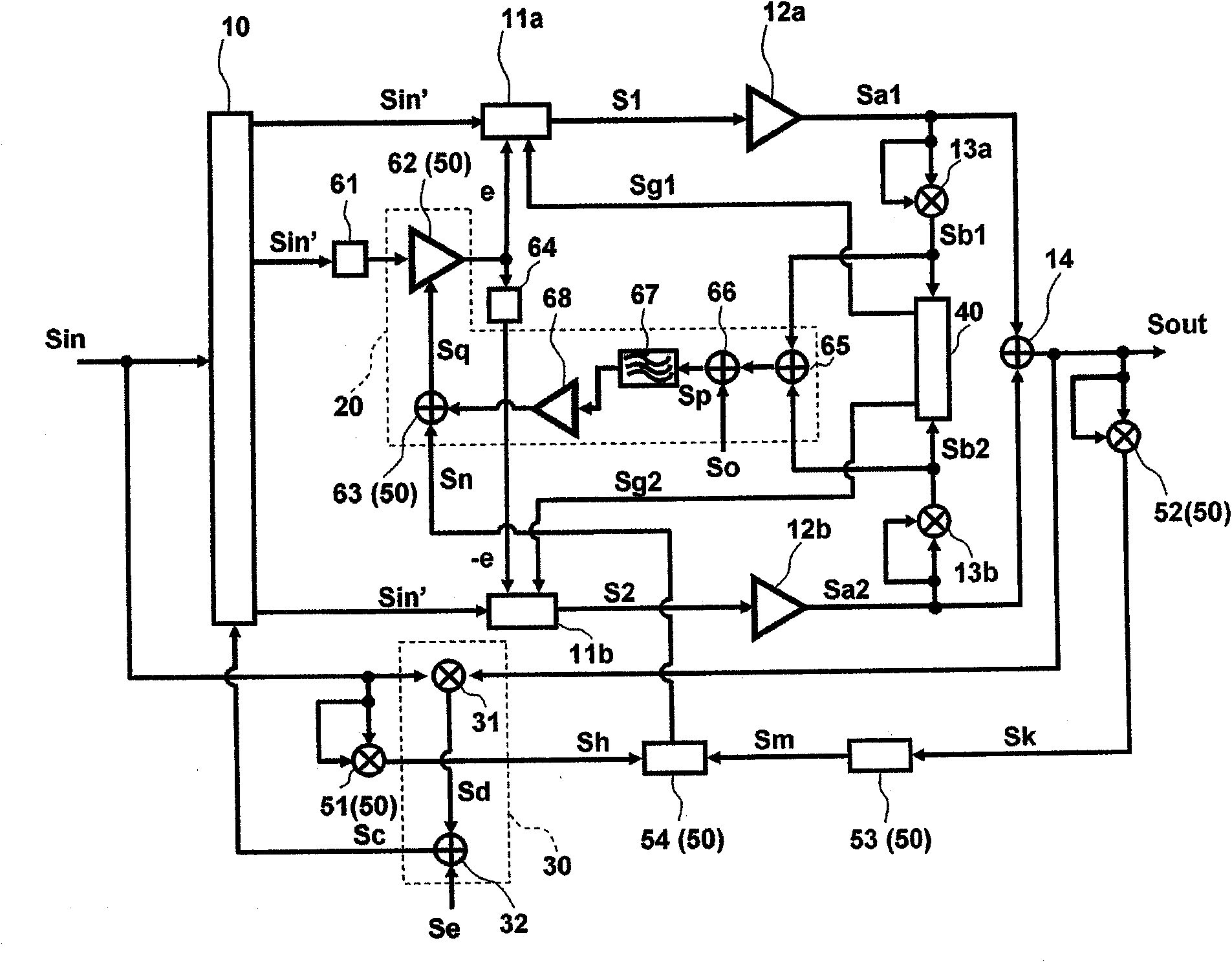
[0029] figure 1 It is a block diagram schematically showing an example of an embodiment of the power amplifying device of the present invention. As shown in the figure, in the power amplifier device of this example, the input signal Sin is input to the variable phase shift circuit 10. The variable phase shift circuit 10 shifts the phase of the input signal Sin according to the phase control signal Sc and outputs it as the basic signal Sin'. The basic signal Sin' is input to the phase shifter 61. The phase shifter 61 is a circuit that advances the phase shift of the basic signal Sin' by π / 2, and its output is input to the variable gain amplifier 62. In the variable gain amplifier 62, the output signal of the adder 63 ...


PUM


Abstract

Provided are a power amplification device which is provided with a function of preventing deviation of the amplitude and phase of an output signal having amplified envelope variation from expected values, and a transmission device and a communication device both using the power amplification device. The power amplification device comprises a variable phase shifter circuit (10) which phase-shifts an input signal; first and second adder circuits (11a), (11b) which generate first and second constant envelope signals; first and second amplifier circuits (12a), (12b); first and second amplitude detection circuits (13a), (13b) which detect amplitudes; a first amplitude control circuit (20) which varies the amplitudes of first and second constant envelope vector generation signals; an output adder circuit (14) which performs vector addition of first and second amplified signals to generate the output signal; a phase shift control circuit (30) which controls the phase shift amount of the variable phase shifter circuit; a gain control circuit (40) which controls the gains of the first and second adder circuits; and a second amplitude control circuit (50) which varies the amplitudes of the first and second constant envelope vector generation signals.

Description

Technical field [0001] The present invention relates to a power amplifying device, a transmitting device and a communication device using the power amplifying device, and more particularly to a method of converting an input signal into two constant envelope signals and performing vector phase after amplifying these constant envelope signals The added power amplifying device and the transmitting device and communication device adopting the power amplifying device. Background technique [0002] The LINC (Linear Amplification with Nonlinear Component) method, among the power amplification methods used in the amplification of the transmission signal in the communication device, converts the input signal with the envelope variation into After inputting two constant envelope signals of phase difference corresponding to the amplitude of the signal, these envelope signals are respectively amplified by nonlinear amplifiers. Moreover, the amplified input signal is obtained by vector addit...

Claims


Application Information

Patent Timeline
Patent Type & Authority Applications(China)
IPC IPC(8): H03F1/06H03F1/32H03F3/24H03F3/68H04B1/04
CPCH03F2203/21142H03F3/24H03F3/211H03F2200/451H03F1/3247H03F3/189H03F1/0294H03F1/3282
Inventor 长山昭福冈泰彦
Owner KYOCERA CORP
Why Eureka
Try Eureka