Beam transmission system and method

A technology of current transmission and beam current, which is applied in the direction of discharge tubes, electrical components, circuits, etc., can solve the problems of beam scanning and focusing, and cannot be realized simultaneously by a single beam optical device, so as to optimize uniformity, improve utilization efficiency, The effect of improving transmission efficiency

Active Publication Date: 2011-06-29
KINGSTONE SEMICONDUCTOR LIMITED COMPANY
View PDF3 Cites 5 Cited by
  • Summary
  • Abstract
  • Description
  • Claims
  • Application Information

AI Technical Summary

Problems solved by technology

[0007] The technical problem to be solved by the present invention is to overcome the defects in the prior art that the scanning and focusing of the beam cannot be simultaneously realized through a single beam optical device, and to provide a method for simultaneously realizing the scanning and focusing of the beam by using a rod-shaped quadrupole magnet. Beam delivery systems and methods

Method used


Image

  • Beam transmission system and method
  • Beam transmission system and method
  • Beam transmission system and method

Examples


Embodiment Construction

[0029] The preferred embodiments of the present invention are given below in conjunction with the accompanying drawings to describe the technical solution of the present invention in detail.

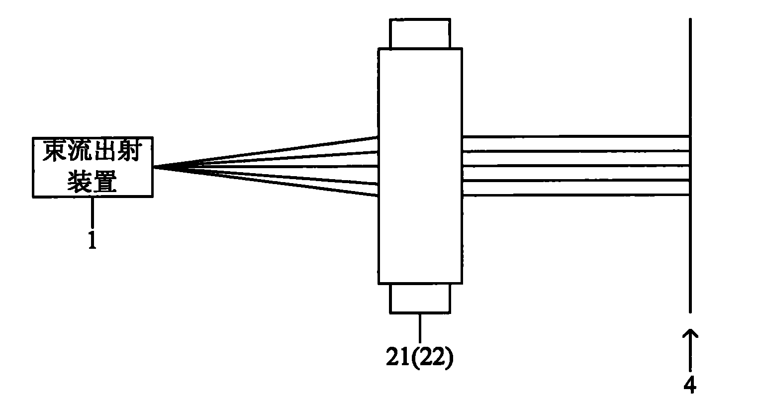
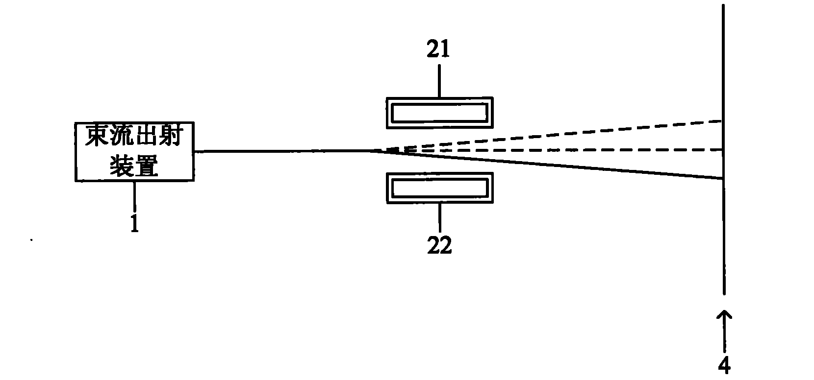
[0030] Figure 1a and Figure 1b Shown are side and top views, respectively, of a first embodiment of the beam delivery system of the present invention. After the beam emitted by the beam emitting device 1 is transmitted on the beam path, it finally reaches the target workpiece 4 according to the preset intensity distribution and angle distribution requirements to complete the processing of the workpiece. The beam emitting device 1 can be an ion source or an electron source, and correspondingly, the transmitted beam can be an ion beam or an electron beam. In the present invention, a pair of first rod-shaped quadrupole magnets 21 and 22 parallel to each other and located on both sides of the beam path are arranged between the beam emitting device 1 and the target workpiece 4 .

[0031] ...


PUM


Abstract

The invention discloses a beam transmission system, which comprises a beam jetting device and a target workpiece as a beam transmission terminal. A pair of parallel first rod-shaped quadrupole magnets positioned on the two sides of a beam path respectively is arranged between the beam jetting device and the target workpiece, the sum of the current values in the coils of the two first rod-shaped quadrupole magnets is kept at a first preset value, and the current value in the coil of each first rod-shaped quadrupole magnet constantly changes between a preset upper limit and a preset lower limit. The invention also discloses a beam transmission method realized by utilizing the beam transmission system. According to the invention, the intensity distribution and the angle distribution of the beam can be controlled by controlling the current values of one or two pairs of rod-shaped quadrupole magnets, so as to improve the beam utilization efficiency and further facilitate the optimization of the dose uniformity and the angle uniformity of the beam. Meanwhile, because of the focusing effect of the rod-shaped quadrupole magnets, the beam transmission efficiency is improved, and the beam intensity when the beam is transmitted to the workpiece is increased.

Description

technical field [0001] The invention relates to the field of semiconductor manufacturing, in particular to a beam transmission system and method. Background technique [0002] Transport control of ion or electron beams is required in many areas of manufacturing. For example, the ion implantation method is used to introduce atoms or molecules, which are usually called impurities, into the target substrate, thereby changing the properties of the substrate material. For example, metal bearings are introduced into other materials through ion implantation, which can improve their wear resistance and prolong their service life. The ion coating method is to deposit ionic materials on the surface of the workpiece, thereby changing the physical and chemical properties of the surface of the workpiece, such as the manufacture of optical devices or display equipment, it is necessary to adopt a thin film deposition process with controllable thickness and predetermined surface properties ...

Claims


Application Information

Patent Timeline
IPC IPC(8): H01J37/30H01J37/32H01J37/147
Inventor 钱锋
Owner KINGSTONE SEMICONDUCTOR LIMITED COMPANY
Why Eureka
Try Eureka