8mm wave dielectric loaded moment circle transition horn antenna

A technology of rectangular transition and medium loading, which is applied in the direction of waveguide speakers, circuits, etc.

Inactive Publication Date: 2011-06-29
BEIJING INSTITUTE OF TECHNOLOGYGY
View PDF1 Cites 11 Cited by
  • Summary
  • Abstract
  • Description
  • Claims
  • Application Information

AI Technical Summary

Problems solved by technology

The research on dielectric-loaded horn antennas excited by circular waveguide is relatively mature, and the research on dielectric-loaded rectangular-circular transitional horn antennas is rarely reported in China.

Method used


Image

  • 8mm wave dielectric loaded moment circle transition horn antenna
  • 8mm wave dielectric loaded moment circle transition horn antenna
  • 8mm wave dielectric loaded moment circle transition horn antenna

Examples


Embodiment Construction

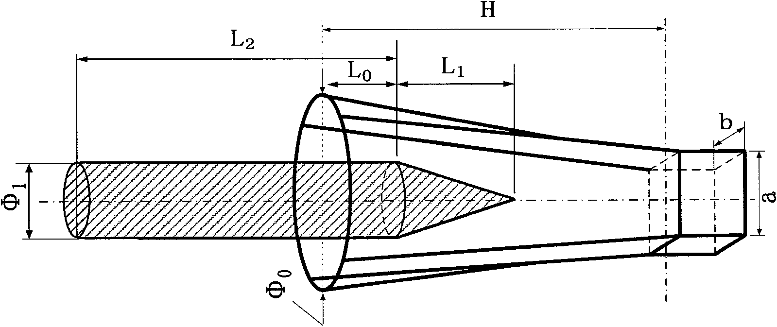
[0023] In order to realize the gradual transformation of the impedance from the air-filled section to the dielectric-filled section in the rectangular transitional waveguide, the part of the dielectric rod extending into the rectangular transitional horn adopts a gradual change structure. Since the wave impedance corresponding to different positions of the rectangular transition section is changing, it is difficult to solve it by analytical method. This patent adopts numerical analysis method to optimize the position L0 where the dielectric rod extends into the rectangular transition horn and the length L1 of the gradual change section.

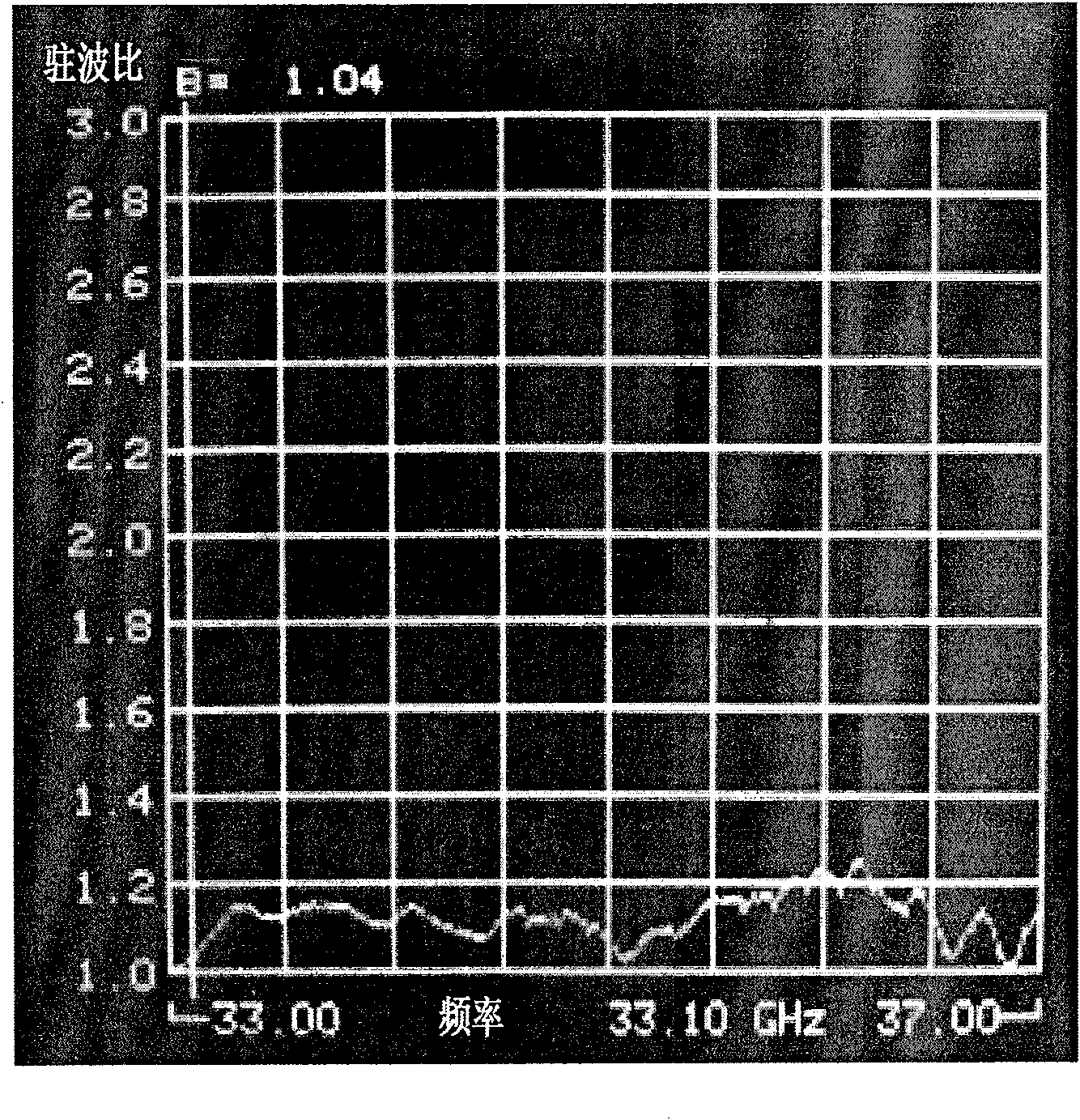
[0024] According to the basic theory of transmission line and antenna radiation theory, although figure 1 All the parameters will affect the antenna radiation characteristics and the input standing wave ratio, but the parameters L0 and L1 are the main factors affecting the antenna input standing wave ratio, the diameter of the dielectric rod Φ...


PUM


Abstract

The invention relates to an 8mm wave dielectric loaded moment circle transition horn antenna. The antenna consists of a rectangular waveguide, a moment circle transition horn and a dielectric rod, wherein a moment circle transition section in the moment circle transition horn is in a smooth transition mode; the dielectric rod consists of a gradient taper section and a uniform cylindrical section, and is coaxial with the moment circle transition horn; the cylindrical section of the dielectric rod is extended into the moment circle transition horn mouth surface and is determined by a numerical analysis method; and the dielectric rod is made of polytetrafluoroethylene and a relative dielectric constant Epsilon r is 2. In the antenna, each parameter of the antenna is optimally designed by a finite element method of a high-frequency structure simulator (HFSS) for an electromagnetic field, so that the antenna can realize a narrow beam width under a smaller caliber, and the input standing wave ratio is high.

Description

field of invention [0001] The invention relates to a horn antenna, in particular to an eight-millimeter-wave medium-loaded rectangular-circle transition horn antenna. technical background [0002] There are two types of millimeter wave imaging: active imaging and passive imaging. Active imaging is what we often call millimeter-wave radar imaging, while passive imaging refers to relying on the atmospheric propagation window of millimeter waves to receive (ground or air) objects and background thermal radiation energy to detect the characteristics of objects and generate high-resolution images. This kind of image can be produced to reflect the difference in temperature and radiation ability of various parts of the scene, so as to observe and analyze the characteristics of the scene. [0003] Compared with active imaging, passive imaging has three advantages: First, passive imaging is obtained by detecting the energy radiated by objects. It is very similar, which is conducive...

Claims


Application Information

Patent Timeline
Patent Type & Authority Applications(China)
IPC IPC(8): H01Q13/02
Inventor 王学田房丽丽
Owner BEIJING INSTITUTE OF TECHNOLOGYGY
Why Eureka
Try Eureka