High-gain horn antenna based on inhomogeneous medium

A non-uniform medium, horn antenna technology, used in antennas, waveguide horns, electrical components, etc., to achieve the effect of improving gain, small length and diameter, and convenient processing

Inactive Publication Date: 2011-06-29
INST OF OPTICS & ELECTRONICS - CHINESE ACAD OF SCI
View PDF2 Cites 45 Cited by
  • Summary
  • Abstract
  • Description
  • Claims
  • Application Information

AI Technical Summary

Problems solved by technology

In order to reduce the phase inconsistency on the mouth surface, the method often used is to change the opening angle of the horn or the length of

Method used


Image

  • High-gain horn antenna based on inhomogeneous medium
  • High-gain horn antenna based on inhomogeneous medium
  • High-gain horn antenna based on inhomogeneous medium

Examples


Embodiment Construction

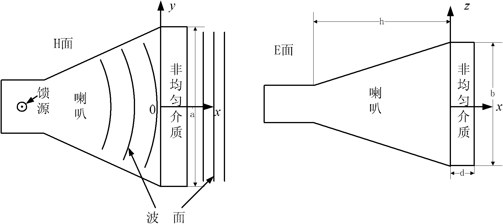
[0026] Such as figure 1 As shown, the specific implementation process of the high-gain horn antenna based on the heterogeneous medium of the present invention is as follows:

[0027] (1) Select the working center frequency of the antenna as 15 GHz, and determine the horn antenna's H surface aperture a=90mm, E surface aperture b=69mm, and horn length h=115mm according to the conventional horn antenna design method.

[0028] (2) Take the thickness of the medium d=8mm, the refractive index of the medium at the coordinate origin is 2.2, and the refractive index at the coordinate origin satisfies Then the refractive index distribution of the inhomogeneous medium is It can be seen from the formula that the distribution of the medium is only uneven in the H plane, and the refractive index at the origin is the largest, which is 2.2, and the refractive index at the edge is the smallest, which is 1.14.

[0029] (3) Since the working wavelength of the antenna is 20mm, the inhomogeneo...


PUM

PropertyMeasurementUnit
Thicknessaaaaaaaaaa

Abstract

The invention discloses a high-gain horn antenna based on an inhomogeneous medium, which is made by the following steps of: (1) determining a central frequency f for the operation of the antenna; (2) designing the ordinary horn antenna operated in the central frequency according to a general designing method for the horn antenna, wherein the aperture of an H side of the antenna is a, the aperture of an E side is b, and the length of a horn is h; (3) determining a refractive index profile n (x, y) of the inhomogeneous medium placed on a mouth surface of the horn; and (4) building the inhomogeneous medium with refractive indexes distributed according to the n (x, y) by using a reverse H-shaped sub-wavelength artificial structural material, and evaluating the structural size of a reverse H-shaped sub-wavelength artificial structural material unit corresponding to each refractive index in a mode of emulation by finite element software.

Description

technical field [0001] The invention designs a horn antenna, especially a high-gain horn antenna based on a non-uniform medium. Background technique [0002] A horn antenna is a directional antenna that can be viewed as an open waveguide. The function of the horn is to generate a uniform phase wavefront on a larger aperture than the waveguide, thereby obtaining high directivity. Due to its design, easy manufacture and relatively low cost, the horn antenna has a wide range of uses in real life. [0003] The main thing that limits the directivity of the horn antenna is the inconsistency of the phase on the face of the horn mouth. When the electromagnetic wave enters the horn throat from the waveguide and reaches the bell mouth surface, the wave surface of the electromagnetic wave changes from a plane to a spherical surface, and the phases of the electromagnetic waves on the bell mouth surface are no longer equal. In order to reduce the phase inconsistency on the mouth surfa...

Claims


Application Information

Patent Timeline
IPC IPC(8): H01Q13/02H01Q15/08
Inventor 杜春雷袁桂山董小春邓启凌
Owner INST OF OPTICS & ELECTRONICS - CHINESE ACAD OF SCI
Why Eureka
Try Eureka