Supercharge Your Innovation With Domain-Expert AI Agents!

Polymer particle, conductive particle, anisotropic conductive material and connection structure

A technology of conductive particles and polymers, applied in the treatment of dyed polymer organic compounds, printed circuits, electrical components, etc., can solve problems such as the deformation of conductive particles, reduce the compressive elastic modulus, improve the compression deformation recovery rate, The effect of reducing the volume expansion coefficient

Inactive Publication Date: 2013-12-11
SEKISUI CHEM CO LTD
View PDF1 Cites 0 Cited by
  • Summary
  • Abstract
  • Description
  • Claims
  • Application Information

AI Technical Summary

Problems solved by technology

Conductive particles are compressed and deformed

Method used


Image

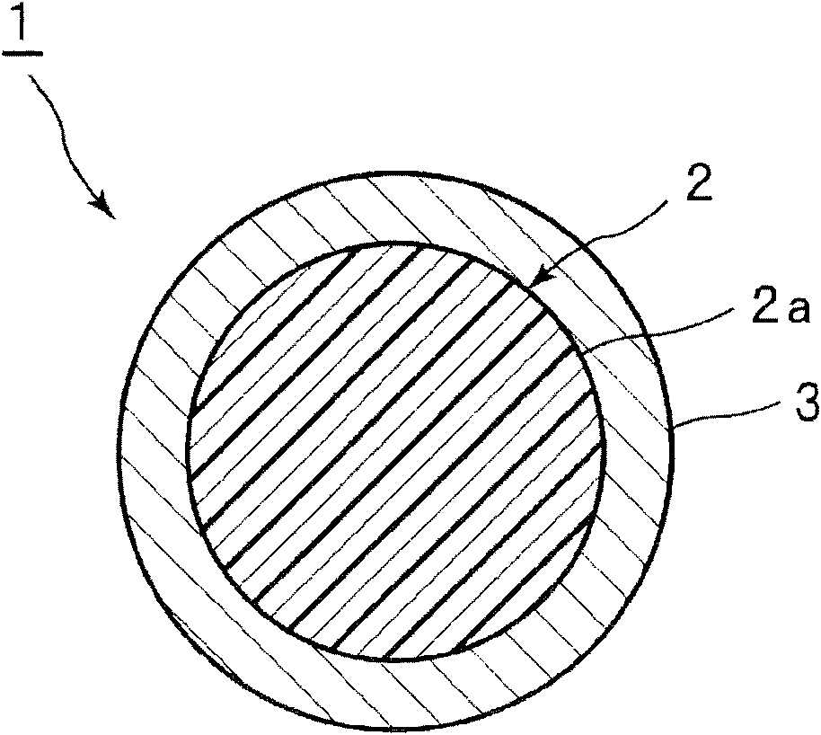
  • Polymer particle, conductive particle, anisotropic conductive material and connection structure
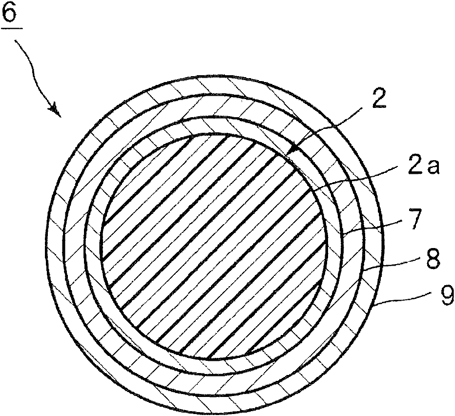
  • Polymer particle, conductive particle, anisotropic conductive material and connection structure
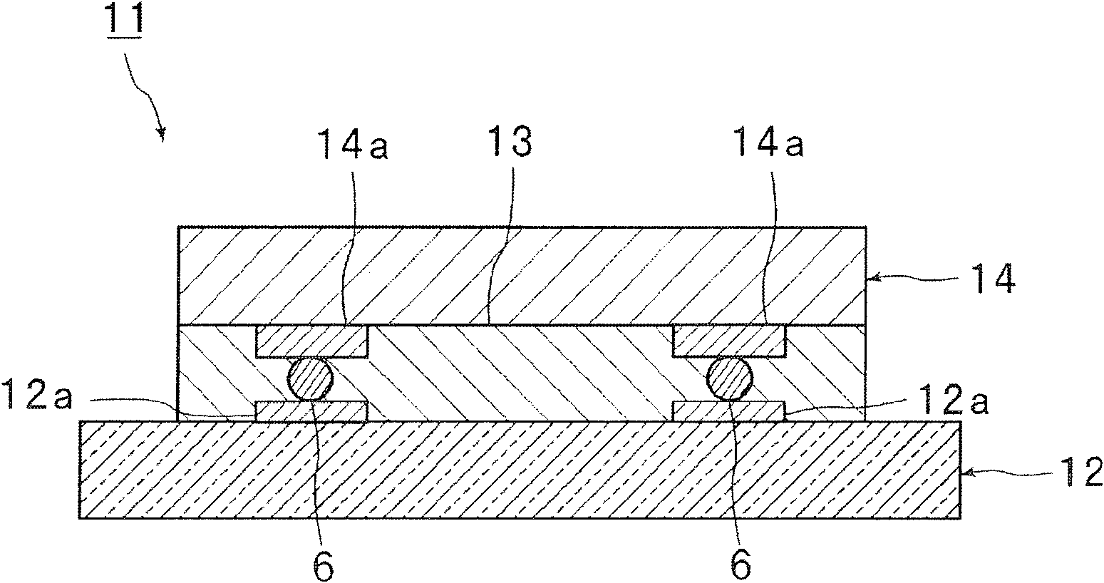
  • Polymer particle, conductive particle, anisotropic conductive material and connection structure

Examples


Embodiment 1

[0197] 55 parts by weight of lauryl acrylate (LA), 45 parts by weight of pentaerythritol tetraacrylate (PTA), and Parts by weight and 3.1 parts by weight of PERBUTYL O (manufactured by NOF Corporation) as a polymerization initiator (the size of the droplets was adjusted to 240 μm) to obtain a mixed solution.

[0198] In a nitrogen atmosphere, polymerization of the obtained mixed solution was performed at 70° C. for 5 hours. Then, the particles were collected by performing suction filtration. The particles were washed with ion-exchanged water and acetone to completely remove the dispersion solvent, and then dried to obtain polymer particles.

Embodiment 2~7 and comparative example 1

[0200] Except having used lauryl acrylate (LA) and pentaerythritol tetraacrylate (PTA) in the ratio shown in following Table 1, it carried out similarly to Example 1, and obtained the polymer particle.

Embodiment 8

[0204] Mix 65 parts by weight of lauryl acrylate (LA), 35 parts by weight of pentaerythritol tetraacrylate (PTA), and 3.1 parts by weight of PERBUTYL O (manufactured by NOF Corporation), and carry out suspension polymerization in a 1% by weight aqueous solution of polyvinyl alcohol, and then implement By classifying, polymer particles were obtained.

[0205] (Evaluation of Examples 1 to 8 and Comparative Examples 1 and 2)

[0206] (1) Compression modulus of polymer particles (10% K value)

[0207] The compressive elastic modulus (10%K value) of the obtained polymer particle was measured by the method mentioned above using the microcompression tester (PCT-100 by Shimadzu Corporation).

[0208] (2) Compression deformation recovery rate of polymer particles

[0209] The compression set recovery rate of the obtained polymer particles was measured by the method described above using a micro compression tester (PCT-100 manufactured by Shimadzu Corporation).

[0210] (3) Volume ex...


PUM

PropertyMeasurementUnit
particle sizeaaaaaaaaaa
thicknessaaaaaaaaaa

Abstract

An object of the present invention is to provide a polymer particulate material with a low compression modulus and a high recovery rate from compression deformation. The present invention provides a polymer particulate material obtainable by co-polymerizing comonomer components including a polyfunctional (meth)acrylate having a structure represented by the below formulas (1), (2) or (3), and a monofunctional (meth)acrylate monomer having a structure represented by the below formula (4), the polymer particulate material shows a recovery rate from compressive deformation of 70% or higher: In the formula (1), n represents an integer within the range of 4 to 10. In the formula (2), R11 represents a hydrogen atom or a C1-4 alkyl group, R12, R13 and R14 each represent a C1-4 alkylene group, and R15, R16 and R17 each represent a hydrogen atom or a methyl group. In the formula (3), R3, R4, R5 and R6 each represent a C1-4 alkylene group, and R7, R8, R9 and R10 each represent a hydrogen atom or a methyl group. In the formula (4), R1 represents a hydrogen atom or a methyl group, and R2 represents a C5-18 alkyl group.

Description

technical field [0001] The present invention relates to a polymer particle, a conductive particle using the polymer particle, an anisotropic conductive material, and a bonded structure. The polymer particle is a polymer particle formed by copolymerization of a monomer, which can be used for example The conductive particles used to connect the electrodes of the parts to be connected are obtained. Background technique [0002] Anisotropic conductive materials such as anisotropic conductive paste, anisotropic conductive ink, anisotropic conductive adhesive (adhesive), anisotropic conductive film, and anisotropic conductive sheet are widely known. In these anisotropic conductive materials, conductive particles are dispersed in paste, ink or resin. [0003] Anisotropic conductive materials have been used for connection between an IC chip and a flexible printed circuit substrate or between an IC chip and a circuit substrate having ITO electrodes, and the like. For example, elect...

Claims


Application Information

Patent Timeline
Patent Type & Authority Patents(China)
IPC IPC(8): C08F220/10C08J3/12
CPCC09C3/10H05K2201/0221C01P2004/84H05K3/323C08F222/1006C08F220/18H05K2201/0218C08F220/1812C08F222/102C08F222/103C08F222/104
Inventor 和田拓也永谷直之
Owner SEKISUI CHEM CO LTD
Features
  • R&D
  • Intellectual Property
  • Life Sciences
  • Materials
  • Tech Scout
  • Unparalleled Data Quality
  • Higher Quality Content
  • 60% Fewer Hallucinations
Learn More