
Lower limb joint rehabilitation training device

A technology of trainers and joints, which is applied in the direction of muscle training equipment, gymnastics equipment, passive exercise equipment, etc., can solve the problems of treatment effects, complex structure, difficult control of technical parameters, etc., and achieve reasonable design and compact structure. Effect

Inactive Publication Date: 2011-07-06
DALIAN JIAOTONG UNIVERSITY
View PDF4 Cites 17 Cited by
  • Summary
  • Abstract
  • Description
  • Claims
  • Application Information

AI Technical Summary

Problems solved by technology

However, none of them got rid of the structural limitations. The range of activities must be limited, and the effect of treatment will be greatly affected. When doing passive rehabilitation training with this lower limb bracket structure, the joints do different translational motions. speed exercise, this type of training does not achieve optimal therapeutic effect
Early passive training after surgery is very necessary, but there is also a problem: due to the lack of active muscle contraction after surgery, patients all have varying degrees of muscle atrophy
Although the above-mentioned technology has made significant progress, its structure is still unreasonable and has deficiencies: it consists of a motor, a worm gear, a transmission mechanism of a worm, a pinion, a spring sleeve, a compression spring, a compression rod, and an external rack holder. The variable stiffness mechanism driven by the motor composed of internal rack and rack fixed frame is not only complex in structure, but also the two springs set on the compression rod are difficult to control the technical parameters and inconvenient to process and manufacture.

Method used


Image

  • Lower limb joint rehabilitation training device
  • Lower limb joint rehabilitation training device
  • Lower limb joint rehabilitation training device

Examples


Embodiment Construction

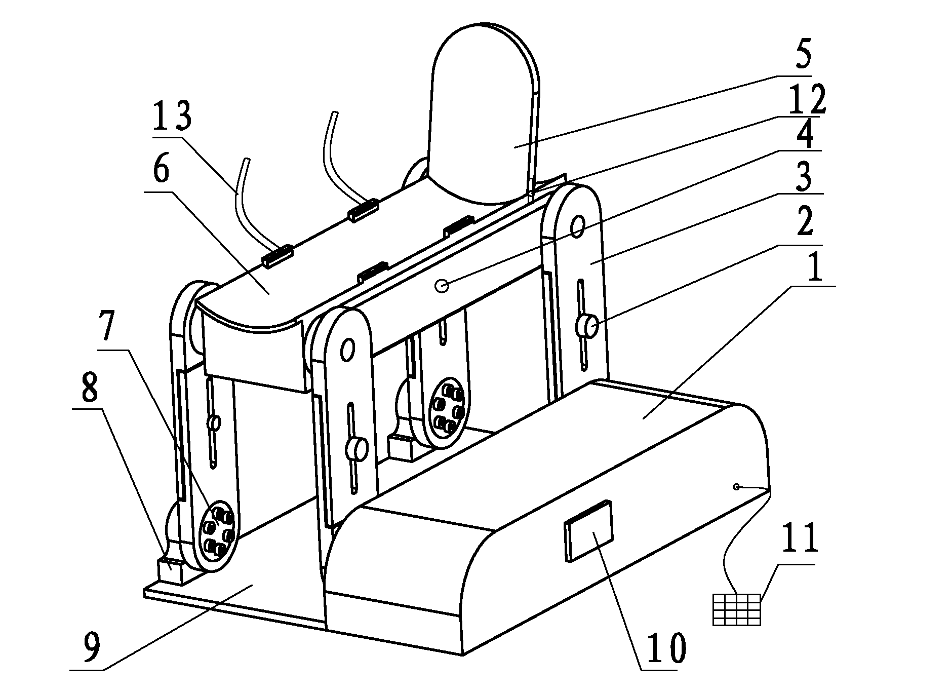
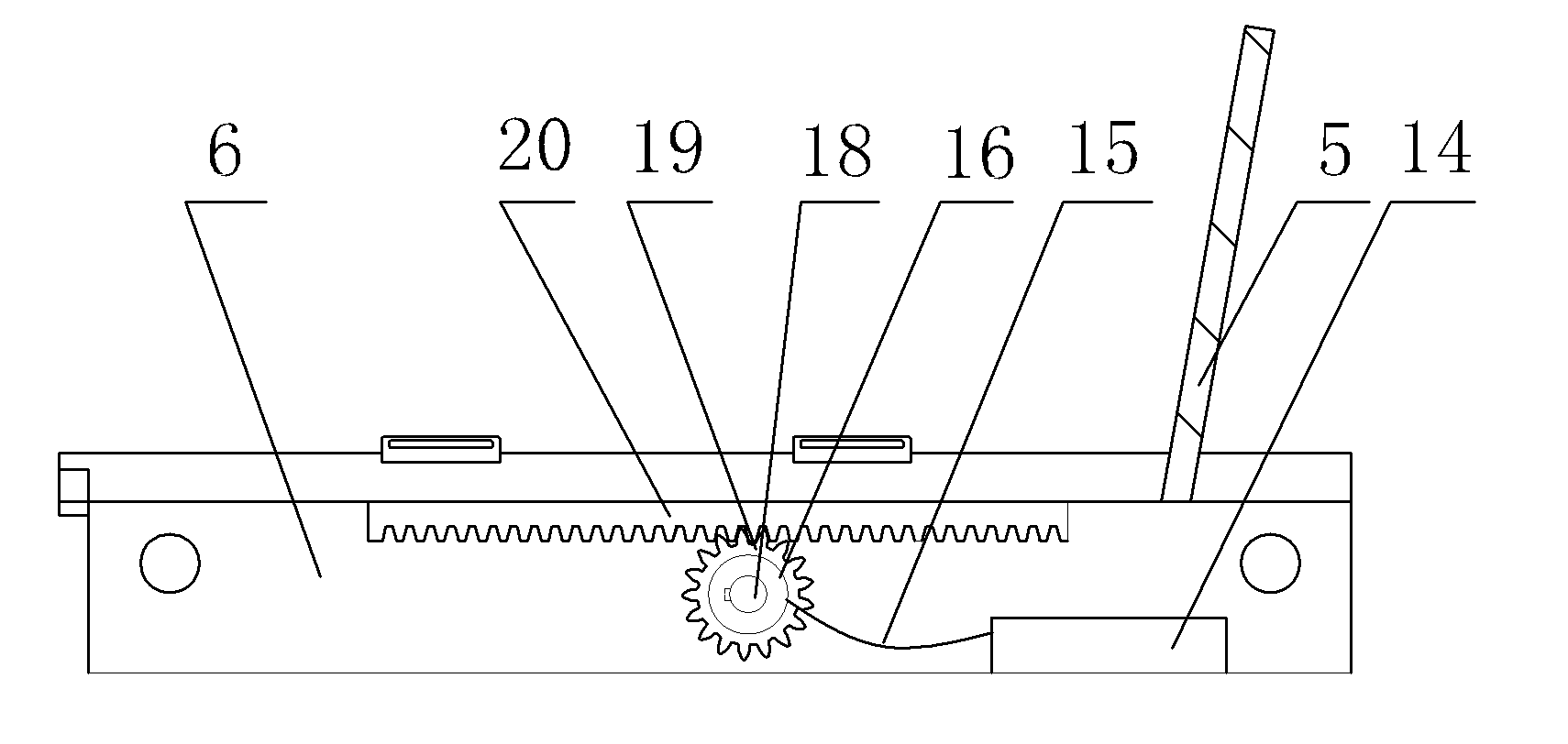
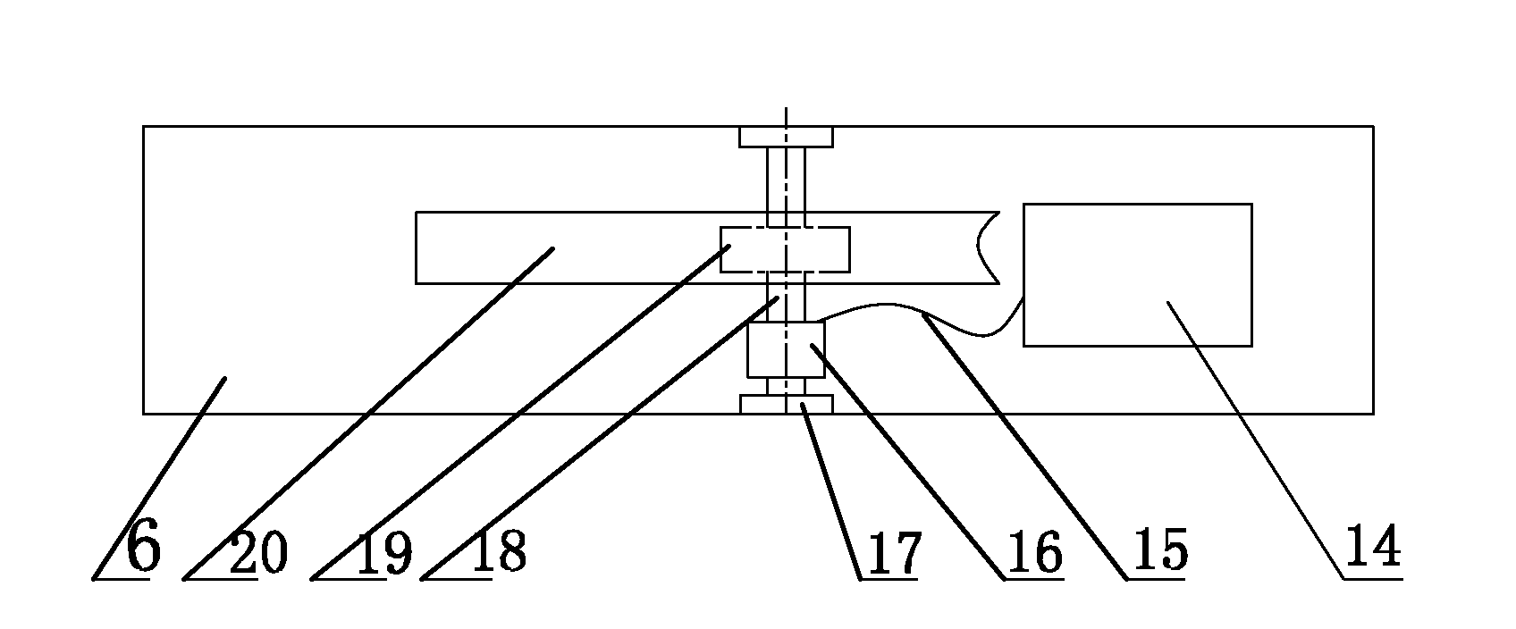
[0018] Such as figure 1 , 2Shown in , 3, 4 is the specific embodiment of the present invention, and its structure comprises: base plate 9, leg rest plate frame 6, bar length adjustment button 2, adjustable leg support 5, adjustable crank 3, variable stiffness mechanism 4, Tensioning coupling sleeve 7, bearing seat 8, display 10, control keyboard 11, leg support fixing knob 12, calf fixing belt 13 and the motor transmission mechanism and control circuit arranged in the casing 1, the motor transmission mechanism in the casing 1 passes through The connecting rod is hinged with four adjustable cranks 3; the two adjustable cranks 3 belonging to the driven are connected to the shaft in the bearing housing 8 through the tensioning coupling sleeve 7; the two adjustable cranks 3 are driven and connected through the tensioning The sleeve 7 is connected with the drive shaft; the base plate 9 is fixed with the bearing seat 8 and the casing 1, and the top of the four adjustable cranks 3 i...


PUM


Abstract

The invention relates to a lower limb joint rehabilitation training device for passive and active exercise training, which comprises a bottom plate, a leg-placing plate, a rod length regulating button, an adjustable leg bracket, a connecting rod, an adjustable crank, a rigidity variable mechanism, a tensioning connecting sleeve, a bearing block, a bottom plate, a display, a control keyboard, a leg bracket fixing knob, a shank fixing belt, a motor transmission mechanism and a control circuit, wherein the motor transmission mechanism and the control circuit are arranged in a shell. The lower limb rehabilitation training device is characterized in that the rigidity variable mechanism driven by a magnetorheological fluid damping brake is arranged at the center of two inner walls of a leg-placing plate frame, wherein the rigidity variable mechanism comprises an exciting current regulator, an exciting current wire, the magnetorheological fluid damping brake, a support shaft seat, a gear shaft, a gear and a rack. Because the rigidity variable mechanism driven by the magnetorheological fluid damping brake is adopted to replace a rigidity variable mechanism driven by a motor, damping forces are set when different patients make active exercise training; and the invention has the advantages of reasonable design, compact structure, convenience for processing, manufacturing and using, and the like.

Description

technical field [0001] The invention belongs to rehabilitation equipment of medical equipment, in particular to a lower limb joint rehabilitation training device for passive and active exercise training. Background technique [0002] At present, the lower limb joint rehabilitation training device in the market is mainly composed of a casing, a lower limb bracket, an adjustable foot bracket, a transmission mechanism and a control mechanism, etc., and the lower limb bracket is a thigh bracket connected by a rotating joint head. and calf support. Drive the lower end of the push rod to reciprocate through the transmission mechanism, drive the lower limb bracket to stretch and bend, so that the affected limb placed on the lower limb bracket can be passively trained, so as to achieve the purpose of rehabilitation treatment. Because the push rod is located under the leg bracket at the end of the telescopic rod at the end of the calf support, when the lower end of the push rod runs...

Claims


Application Information

Patent Timeline
IPC IPC(8): A63B21/008A63B23/04A61H1/00
Inventor 王广欣赵楠
Owner DALIAN JIAOTONG UNIVERSITY
Learn More