Device for separating pollutant in garbage leachate

A technology of landfill leachate and gas-liquid separation device, which is applied in the direction of water/sewage multi-stage treatment, heating water/sewage treatment, water/sludge/sewage treatment, etc., and can solve the problem of high process cost, unreachable, and polluted environment and other problems to achieve the effect of small size and lower operating costs

Inactive Publication Date: 2011-07-06
李虹
View PDF0 Cites 8 Cited by
  • Summary
  • Abstract
  • Description
  • Claims
  • Application Information

AI Technical Summary

Problems solved by technology

[0004] There is also a method of solidifying landfill leachate with an organic curing agent. The solidified product produced by this method will liquefy again and pollute the environment.
[0005] The existing garbage permeate filtrate concentrate obtained by evaporation method either has high process costs, or increases the cost of subsequent storage, solidification or incineration because the concentration cannot reach a certain level.

Method used


Image

  • Device for separating pollutant in garbage leachate
  • Device for separating pollutant in garbage leachate
  • Device for separating pollutant in garbage leachate

Examples


Embodiment 1

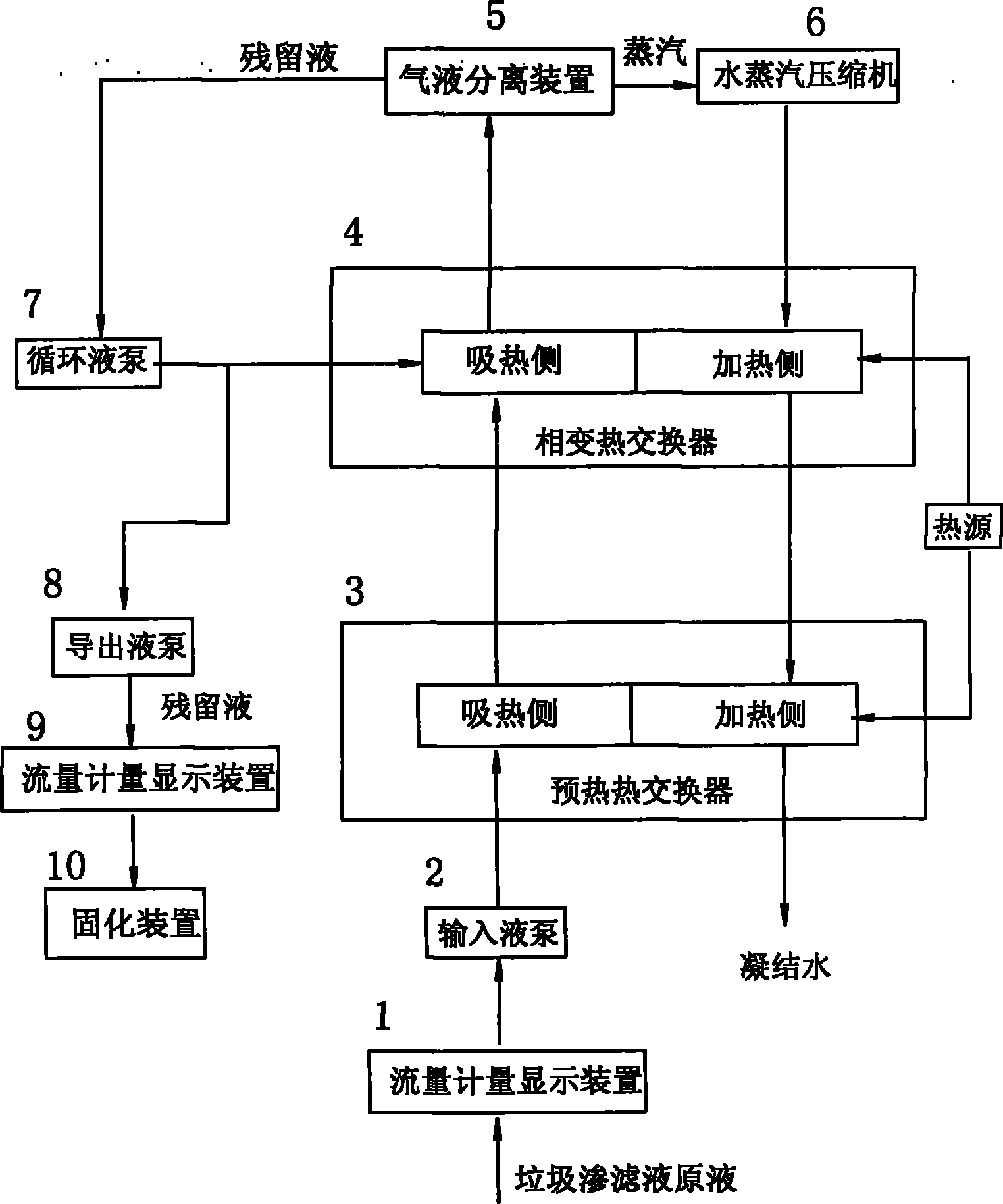
[0028] This example is a device system connected by pipelines for the separation of pollutants in landfill leachate. The structure of the system is:

[0029] There is an input liquid pump 2 with a flow quantitative and adjustment control device, its input channel is connected with a flow measurement display device 1, and its output end is connected with the input end of the heat absorption channel of the preheating heat exchange device 3;

[0030] The preheating heat exchange device 3 is a plate evaporator, and the heat-absorbing channel and the heat-releasing channel are separated by a heat transfer wall;

[0031] The output end of the heat absorption channel of the preheating heat exchange device 3 is connected to the input end of the heat absorption channel of the phase change heat exchange device 4;

[0032] The phase-change heat exchange device 4 is a plate evaporator, which separates the heat-absorbing channel from the heat-releasing channel through a heat transfer wall,...

Embodiment 2

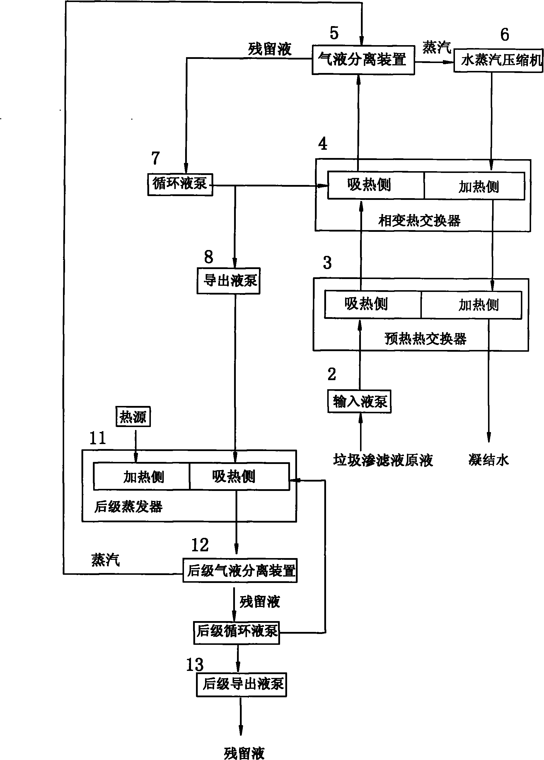
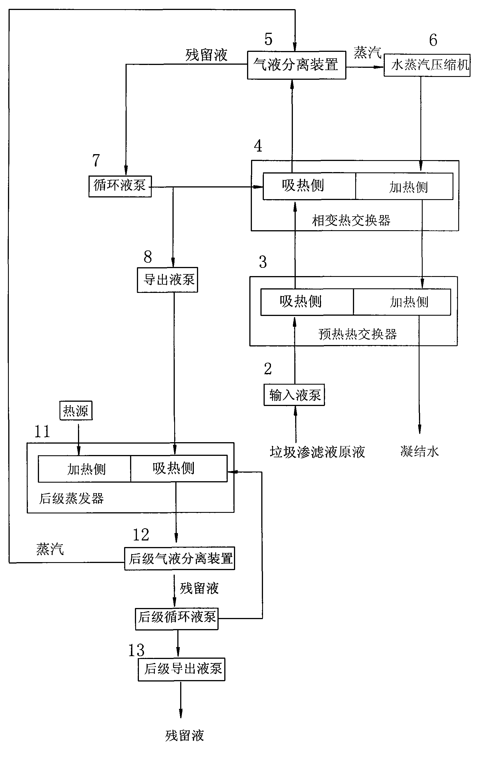
[0039] The difference with embodiment 1 is:

[0040] In this example, a first-stage post-stage evaporator 11 (multi-stage can also be set) is set at the rear of the outlet liquid pump 8, specifically:

[0041] The output end of the export liquid pump 8 is connected to the heat absorption channel of the rear-stage evaporator 11, the output end of the heat absorption channel is connected to the input end of the subsequent gas-liquid separation device 12, and the steam output end of the rear-stage gas-liquid separation device is connected to the upstream steam channel The liquid output end of the second-stage gas-liquid separation device is connected to the residual liquid output end through the second-stage export liquid pump 13, and the heating side of the latter-stage evaporator 11 is provided with a heat source.

[0042] The upstream water vapor passage may be the phase change heat exchange device 4, or the gas-liquid separation device 5, or the water vapor compressor 6, or t...


PUM


Abstract

A device for separating pollutants in garbage leachates is provided with an input liquid pump connected in turn by pipelines, an endothermic channel of a preheating heat exchange device, an endothermic channel of a phase transition heat exchange device, and a gas-liquid separation device; a gas output terminal of the gas-liquid separation device is connected in turn to a water vapor compressor, a heating channel of the phase transition heat exchange device, a heating channel of the preheating heat exchange device, and a condensate water output terminal; a liquid output terminal of the gas-liquid separation device is connected to the endothermic channel output terminal of the phase transition heat exchange device by a circulating liquid pump, and an output terminal of the circulating liquid pump is connected to a residual liquid output terminal by a derivation liquid pump. The invention can increase the concentration of the pollutants separated from garbage leachates and decrease the volume so as to realize the economical and complete sealing disposal of the pollutants and realize the zero discharge of the pollutants. Meanwhile, the invention can realize the complete recovery and recycling of latent heat and sensible heat, can greatly decreace the operation cost, and has the advantages of high efficiency, saved energy, and reduced consumption.

Description

technical field [0001] The invention belongs to the technical field of sewage treatment, and in particular relates to a treatment device for landfill leachate. Background technique [0002] Landfill leachate has a high concentration of pollutants, complex components, poor biodegradability, and its environmental hazard ability is 100-200 times higher than that of urban sewage. It is known as the number one killer of the environment. If the leachate cannot be effectively treated, it will seriously pollute the ecological environment and water resources, and endanger public health and safety. [0003] In the field of landfill leachate treatment, various sewage treatment methods such as "physical treatment / chemical treatment / biological treatment / reverse osmosis membrane" have been used to treat landfill leachate, which will produce a large amount of high-concentration liquid that cannot be disposed of. The result is only the transfer of pollution in space and time. [0004] The...

Claims


Application Information

Patent Timeline
Patent Type & Authority Applications(China)
IPC IPC(8): C02F9/10C02F1/04
Inventor 李虹
Owner 李虹
Why Eureka
Try Eureka