
Method for diagnosing accidental fire of gasoline engine

A diagnostic method, gasoline engine technology, applied in the direction of engine ignition, mechanical equipment, engine components, etc., can solve problems such as difficulties, high price of pressure sensors, and short service life of sensors

Inactive Publication Date: 2015-01-21
FAW GROUP
View PDF5 Cites 1 Cited by
  • Summary
  • Abstract
  • Description
  • Claims
  • Application Information

AI Technical Summary

Problems solved by technology

[0005] The in-cylinder pressure method detects the misfire according to the characteristic that the cylinder pressure has a large difference between the misfire and the normal combustion. The advantage is that it is more accurate. use is restricted;
[0006] The ignition voltage waveform method detects misfire according to different combustion conditions, and the characteristics of the spark plug discharge voltage waveform are very different. The advantages are convenient installation and strong adaptability. The impact of spark plug insulation performance, so the detection accuracy is not high;
[0007] The oxygen sensor method is generally used in cars with three-way catalytic converters. When the mixture is rich, the oxygen sensor outputs high voltage, and when the mixture is lean, it outputs low voltage. When the mixture is lean, the oxygen sensor voltage drops to the lowest value. Nearby, the misfire fault can be diagnosed by the oxygen sensor method, but because the output voltage is very sensitive to the change of the air-fuel ratio, this method is not reliable;
[0008] The ion current method uses an external bias voltage to use the ions and free electrons generated by the combustion of the mixture gas when the spark plug is ignited. Under the bias voltage, the ions and free electrons are translated to form a current, and the ion and electron concentrations change continuously with the combustion process. The advantage of detecting misfire is that it can not only detect misfire, but also detect knock and gas distribution phase and provide air-fuel ratio information, but the cost is very high, and it is still difficult to implement

Method used


Image

  • Method for diagnosing accidental fire of gasoline engine
  • Method for diagnosing accidental fire of gasoline engine
  • Method for diagnosing accidental fire of gasoline engine

Examples


Embodiment 1

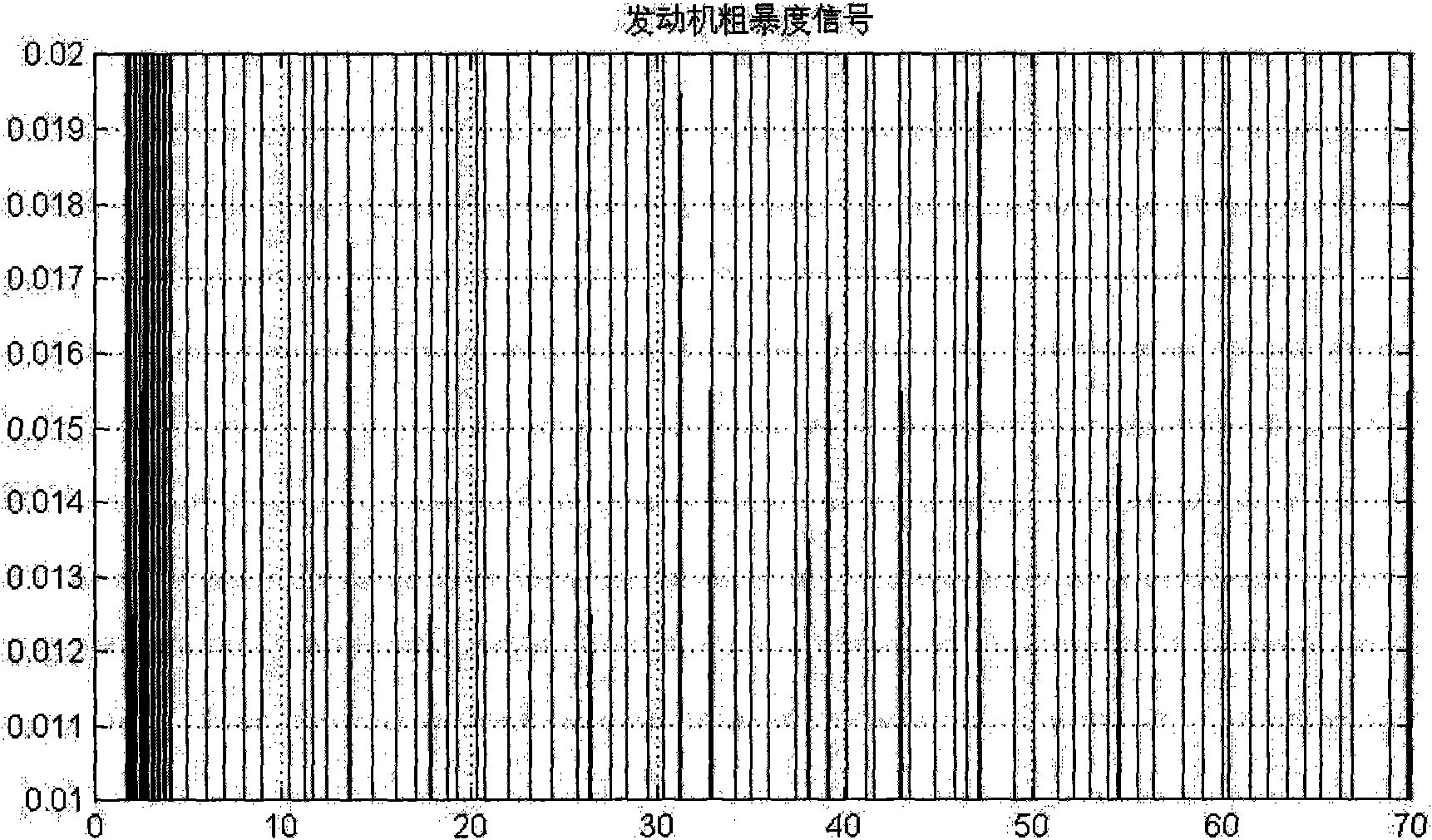
[0072] Such as figure 2 As shown, it is the engine speed fluctuation signal in the case of 2% misfire rate under the condition of 3000 rev / min. Because the emissions caused by the misfire rate are within the allowable range of OBD regulations, the system does not report a misfire failure;

Embodiment 2

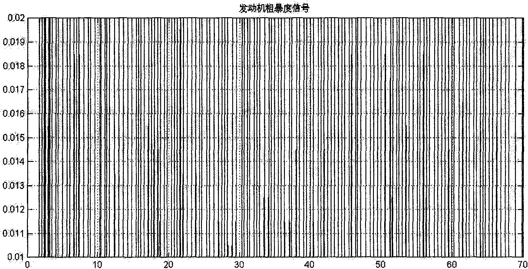
[0074] Such as image 3 As shown, under the condition of the speed of 3000 rpm, there is a fluctuation signal of the engine speed in the case of a 5% misfire rate. The system detects a misfire and reports a fault because the emissions due to the rate of misfire are outside the limits allowed by OBD regulations.


PUM


Abstract

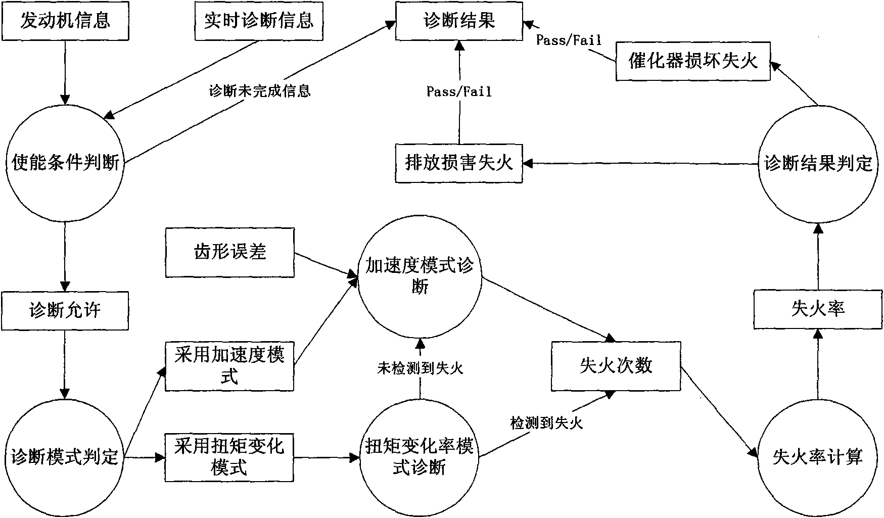
The invention relates to a method for diagnosing accidental fire of a gasoline engine. The method is characterized by comprising the following steps of: computing the moment deviation of a crankshaft by using a formula, namely delta T = (T2-T1)-(T1-T0), wherein the delta T is the moment deviation of the crankshaft, the T2 is the current ignition moment, the T1 is the last ignition moment, and the T0 is the ignition moment before the T1; judging the magnitude of the fluctuated value of the rotation speed; if the fluctuated value is overlarge, judging whether a circuit is broken or the accidental fire occurs; if the accidental fire occurs, judging whether a single cylinder catches fire or multiple cylinders catch fire; if the single cylinder catches fire, judging the serial number of the cylinder which catches fire, wherein all accidental fire is required to be subjected to statistic analysis to acquire an accidental fire degree evaluation report; judging the accidental fire is caused relevant to gasoline discharge or the damage of a catalytic converter; and finally reporting faults, finishing testing and storing the faults.

Description

Technical field: [0001] The invention relates to a gasoline engine misfire diagnosis method, which belongs to the field of automotive electronics development. Background technique: [0002] On July 1, 2008, the third phase of GB18352.3-2005 "Light Vehicle Pollutant Emission Limits and Measurement Methods (China Phase III, IV)" emission regulations began to be implemented. Compared with the previous regulations, the main change this time is to increase On-board diagnostics (OBD) system requirements are specified, requiring at least online diagnosis of misfires, three-way catalytic converters, oxygen sensors, and all emission-related sensor actuators. [0003] Engine misfire will produce a large amount of unburned hydrocarbon exhaust gas. Some hydrocarbons will react with excess oxygen in the catalyst and cause the catalyst to be overheated and damaged. Therefore, misfire will not only affect emissions, but also damage the catalyst. Misfire is a mandatory inspection item in e...

Claims


Application Information

Patent Timeline
Patent Type & Authority Patents(China)
IPC IPC(8): F02P17/00
Inventor 颜松孙鹏远
Owner FAW GROUP
Learn More