Check valve device of vortex compressor

A technology of scroll compressors and check valves, applied in the field of scroll compressors, can solve problems such as the inability to solve high-pressure gas backflow, achieve the effects of preventing reverse rotation, reducing impact or impact, and improving reliability

Active Publication Date: 2013-05-08
GD MIDEA HEATING & VENTILATING EQUIP CO LTD
View PDF1 Cites 0 Cited by
  • Summary
  • Abstract
  • Description
  • Claims
  • Application Information

AI Technical Summary

Problems solved by technology

However, due to the fixed existence of the movement stroke of the valve plate, the existing technology cannot solve the high-pressure gas backflow, and the resulting reverse noise and reliability problems

Method used


Image

  • Check valve device of vortex compressor
  • Check valve device of vortex compressor
  • Check valve device of vortex compressor

Examples


no. 1 example

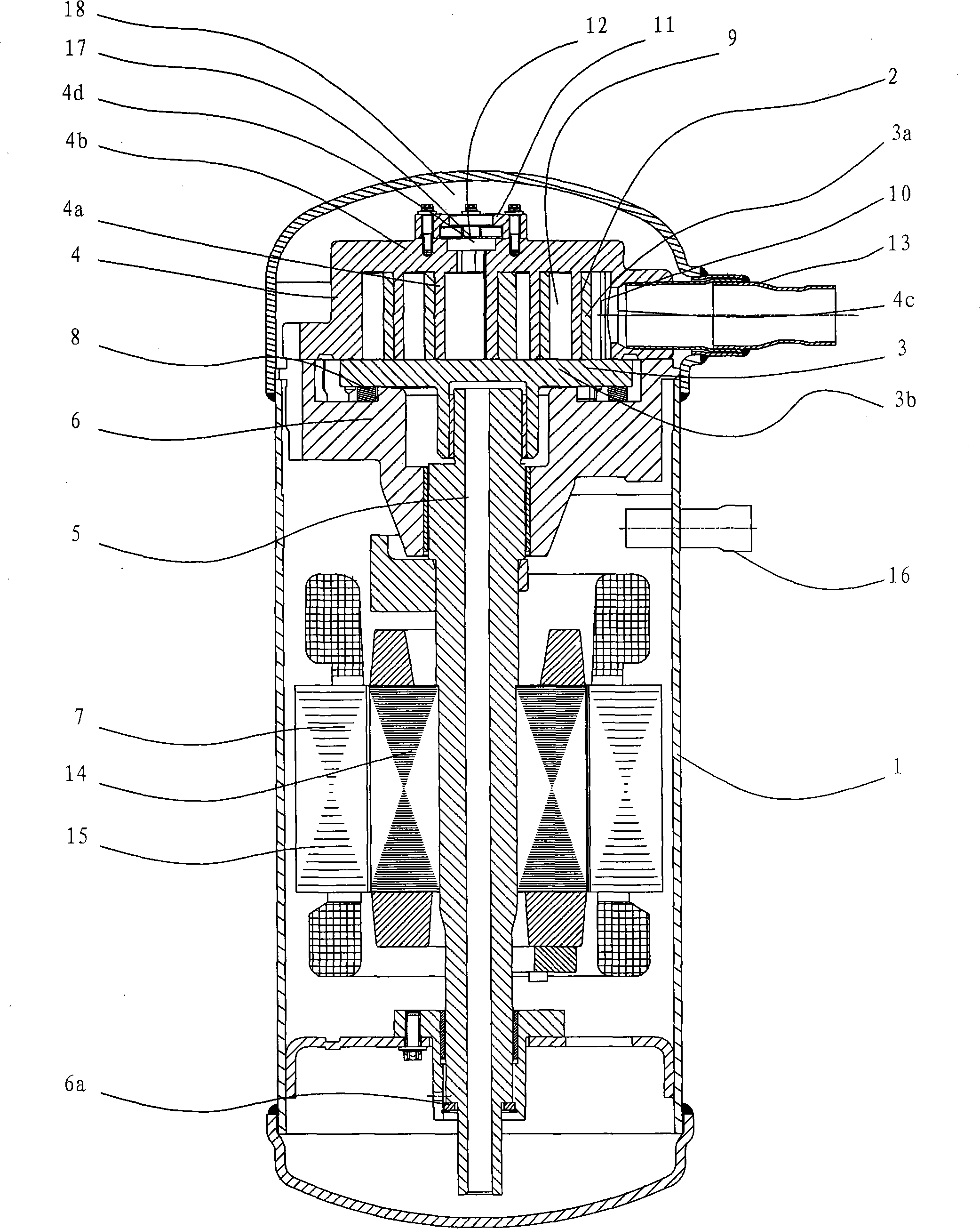
[0034] see figure 2 , is the vertical section view of the scroll refrigeration compressor.

[0035] In the scroll compressor, the compression mechanism unit 2 and the motor unit 7 are connected by a crankshaft 5 and accommodated in the airtight container 1 . The compression mechanism part 2 includes a fixed scroll 4 , a movable scroll 3 , a frame 6 , a crankshaft 5 and an Oldham slip ring 8 as main components.

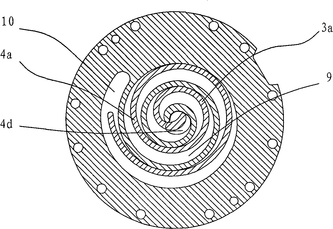
[0036] The fixed scroll 4 has a fixed scroll end plate 4b and a spiral fixed scroll 4a standing upright on the fixed scroll end plate 4b. The fixed scroll 4 is fastened on the upper side of the frame 6 by screws. The periphery of the frame 6 is fixed on the airtight container 1, and the lower part of the airtight container 1 has a bearing 6a for supporting the rotation of the crankshaft 5. A suction port 4c is provided on the outer peripheral portion of the fixed scroll 4 . The suction port 4c is parallel to the fixed scroll end plate 4b. A suction pipe 13 connec...

no. 2 example

[0052] see Figure 9 , the elastic buffer device includes a valve seat composed of an upper valve seat 11f and a lower valve seat 11g, the shoulder 11m and the air return hole 11d are located on the upper valve seat 11f, and the upper valve seat and the lower valve seat 11g together form a guide inner hole 11c and an annular positioning groove, the cross section of which is ∩ or ∏-shaped; the second buffer piece 11h is ring-shaped, and the cross section of the second buffering piece 11h is ∩ or Π-shaped, and the outer side of the second buffering piece 11h is embedded Located in the positioning groove, the inner side of the second buffer member 11h is located in the guide inner hole 11c, and the inner diameter of the second buffer member 11h is smaller than the outer diameter of the valve plate 12 and larger than the inner diameter of the air return hole 11b.

[0053] The outer side of the shoulder 11m is provided with a discharge port 11e, the discharge port 11e is located on...

no. 3 example

[0059] see Figure 10 , the elastic buffer device includes a third buffer member 11k, the third buffer member 11k is located in the guide hole 11c and fitted under the shoulder 11m, the third buffer member 11k is ring-shaped, and the inner diameter of the third buffer member 11k is less than The outer diameter of the valve plate 12 is greater than the inner diameter of the air return hole 11b, and the outer wall of the third buffer member 11k is attached to the inner wall of the guide inner hole 11c. A discharge port 11e is provided on the outside of the retaining shoulder 11m, and the discharge port 11e is located on the valve seat 11. A communication channel 11j communicating with the discharge port 11e is provided at the lower part of the guide inner hole 11c, and the communication channel is located below the third buffer member 11k.

[0060] The bonding in this embodiment can be directly bonded with an adhesive, or a plurality of small pits can be dug under the shoulder, ...


PUM


Abstract

The invention discloses a check valve device of a vortex compressor, which comprises a valve seat and a piston valve sheet, wherein a guiding inner hole which is used for leading the valve sheet to move is formed in the valve seat; the valve seat is fixed on a static vortex disc; the discharge hole of the guiding inner hole is communicated with the discharge hole of the static vortex disc; a blocking shoulder is arranged at the upper end of the valve seat; an air return hole is formed in the center of the blocking shoulder; the valve sheet is used for doing up-and-down motion along the guiding inner hole of the valve seat; an elastic damping device which is used for damping the upward movement of the valve sheet is arranged in the valve seat, is positioned below the blocking shoulder and comprises an annular positioning groove which is formed on the top of the inner wall of the guiding inner hole; the positioning groove is positioned below the blocking shoulder; and a first damping piece is annular. The invention has the characteristics that: the device has a simple and reasonable structure; and abnormal noise caused by impacting the motion-stopping surface and the side wall of the valve seat through the valve sheet can be prevented, and the fall back speed of the valve sheet can be increased to greatly reduce gas reflux, so that the reversed rotation of the compressor is alleviated, and the reliability of the compressor is improved.

Description

technical field [0001] The invention relates to a scroll compressor, in particular to a check valve device of the scroll compressor. Background technique [0002] In the disclosed technology, there is a piston-type valve plate that is movably placed in a valve seat and can move up and down in the valve seat to prevent the compressor from shutting down due to gas backflow. The resulting compressor rotates in reverse. During the working process of a compressor with a common piston check valve, when the discharge pressure Pd is lower than the initial discharge pressure Pp of the fixed scroll, the pressure at the bottom of the valve plate is higher than the pressure at the top, so the valve plate is lifted up and move to the seat thrust shoulder. If the pressure ratio (discharge pressure / suction pressure) increases, the initial discharge pressure Pp of the fixed scroll becomes lower than the discharge pressure Pd. At this time, the valve plate moves to the exhaust port of the...

Claims


Application Information

Patent Timeline
Patent Type & Authority Patents(China)
IPC IPC(8): F04C18/02F04C29/12
Inventor 邵海波
Owner GD MIDEA HEATING & VENTILATING EQUIP CO LTD
Why Eureka
Try Eureka