
Cross-flow fan of composite wire blade impeller

A blade impeller, cross-flow fan technology, applied in mechanical equipment, machines/engines, liquid fuel engines, etc., can solve the problems of not being able to independently take values ​​​​one by one, and it is difficult to ensure the output and efficiency of the impeller, and achieve the effect of diversity.

Active Publication Date: 2011-07-06
深圳市科力尔运动控制技术有限公司
View PDF11 Cites 10 Cited by
  • Summary
  • Abstract
  • Description
  • Claims
  • Application Information

AI Technical Summary

Problems solved by technology

In recent years, in order to improve the external performance and efficiency of the cross-flow fan, a lot of research has been done on the main geometric parameters of the cross-flow fan impeller, and some results are expected, but most of these studies focus on the angle of the inner peripheral blade, the outer peripheral blade Angle, diameter ratio, relative grid pitch and casing components, etc., due to the blade profile radius, blade outer peripheral angle, blade inner peripheral angle, chord length of blade profile and impeller outer peripheral pitch, relative grid pitch and diameter ratio, etc. The geometric parameters are interrelated and cannot be taken independently one by one. It is difficult to ensure that the main geometric parameters can obtain the most reasonable values ​​and ensure the best output and efficiency of the impeller.

Method used


Image

  • Cross-flow fan of composite wire blade impeller
  • Cross-flow fan of composite wire blade impeller
  • Cross-flow fan of composite wire blade impeller

Examples


Embodiment Construction

[0028] The present invention will be further described below in conjunction with the accompanying drawings and embodiments. The following description is by way of example, but the protection scope of the present invention should not be limited thereto.

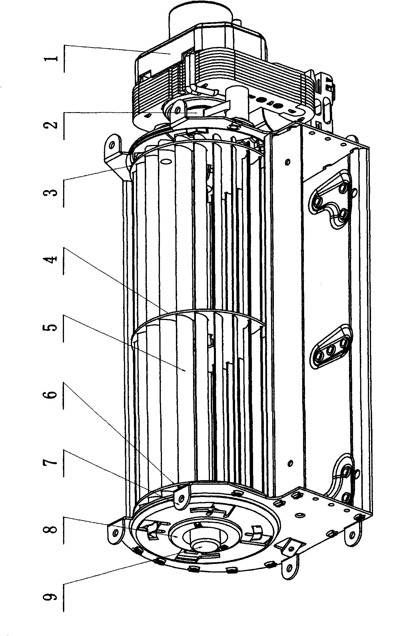
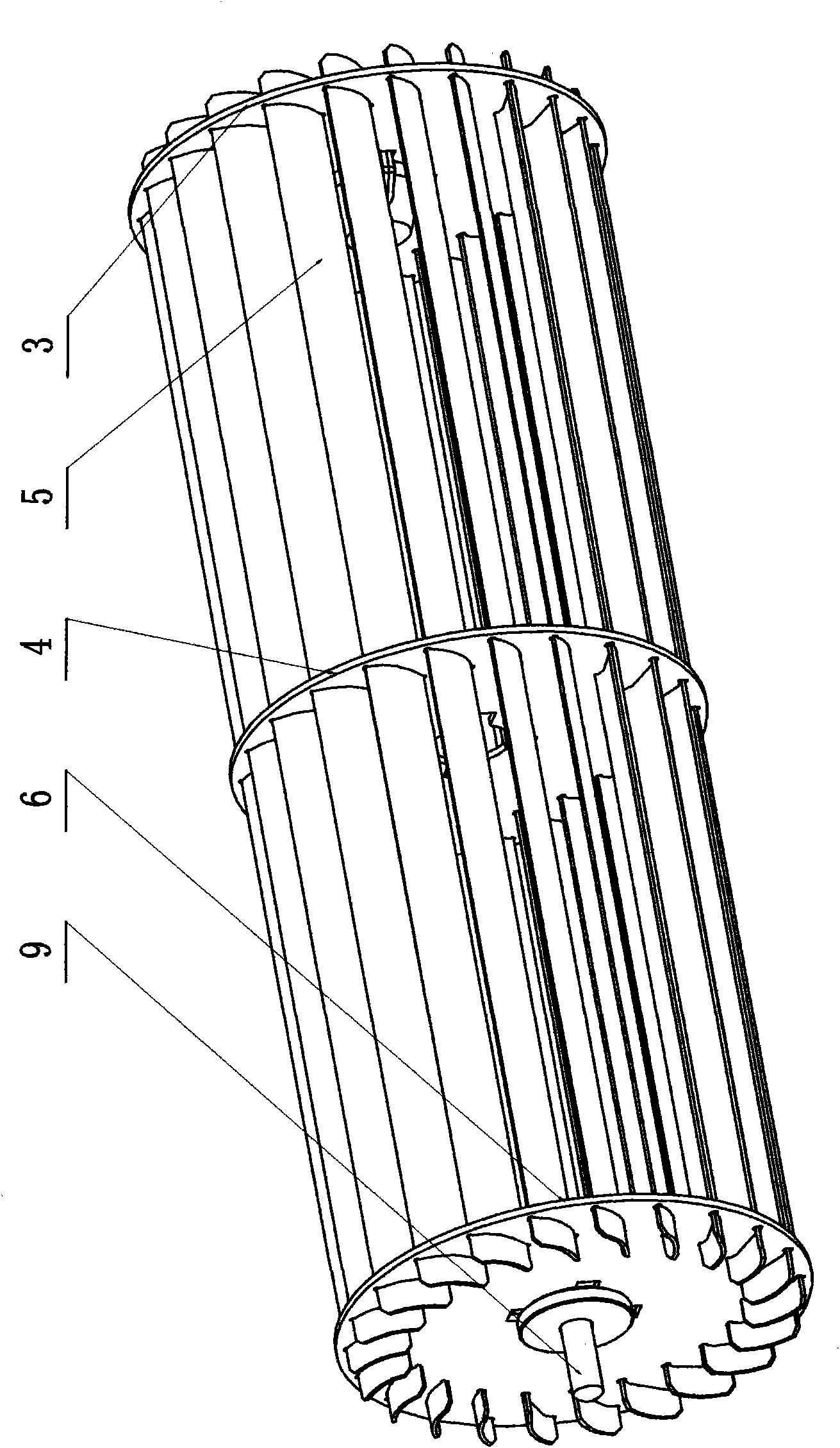
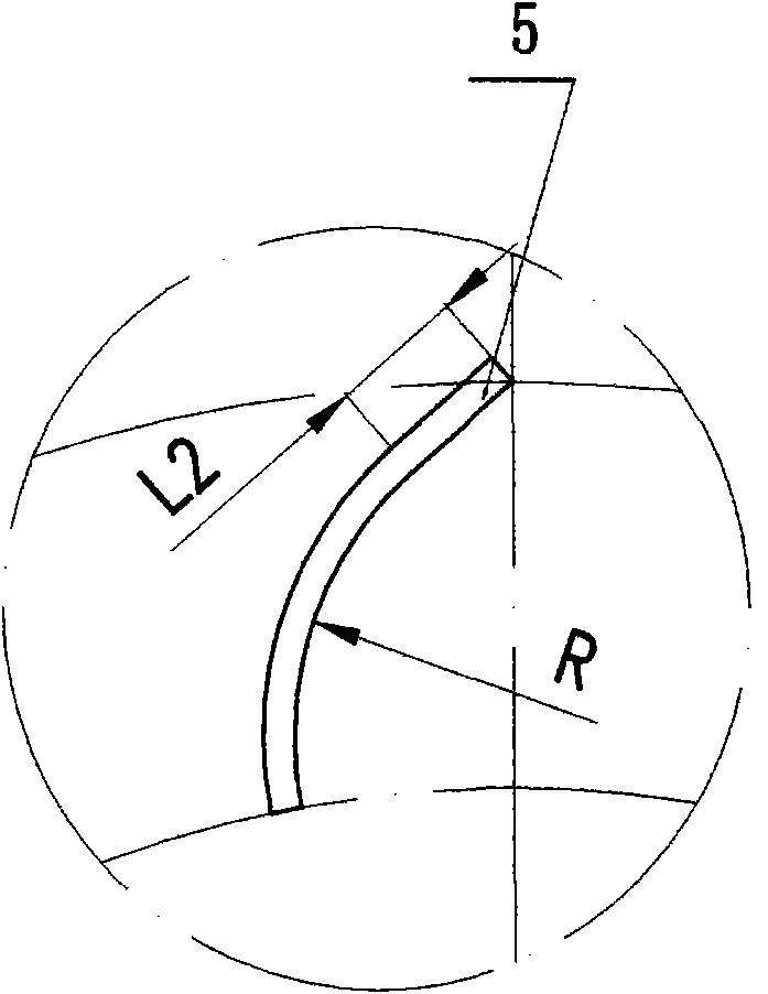
[0029] This embodiment is composed of a motor 1, a coupling 2, a cross-flow impeller, a casing assembly 7 and a bearing seat 8. The main arc section profile of the worm plate of the casing assembly 7 is an eccentric arc, and the casing assembly 7 consists of a volute The shell plate, the volute tongue plate and the side plates at both ends are riveted into a whole. The bearing seat 8 is installed in the middle hole of the two end side plates of the casing assembly 7 . The cross-flow impeller is composed of a left disc 6, a middle disc 4, a right disc 3, an impeller shaft 9, and blades 5 (the number of blades can be 20 to 27 pieces), and the internal shape line of the blade 5 is a (middle) segment The two ends of the arc (tha...


PUM


Abstract

The invention discloses a cross-flow fan of a composite wire blade impeller, which relates to the technical field of electro-machinery. The fan consists of a motor 1, a coupler 2, an impeller, a shell assembly 7 and a bearing seat 8, wherein the impeller consists of a left wheel disc 6, a middle wheel disc 4, a right wheel disc 3, an impeller shaft 9 and more than two blades 5; and the cross section internal mold line of each blade 5 is a composite mold line which is formed in a mode that a section of arc is tangent with an outer circumferential straight-line segment or a section of arc is tangent with an inner circumferential straight-line segment. The fan has the characteristics that: the total pressure efficiency is greatly improved, the noise is obviously reduced compared with that of a sound level A, and the like, is suitable for cooling radiation of various types of equipment, ventilation of rooms, public places and vehicles, constant temperature and drying machines, room cooling and heating equipment and household electrical appliances such as a freezing and showing cabinet, a cool air fan, a warm air blower, an electrical fireplace, an air curtain machine, an embedded oven and the like.

Description

technical field [0001] The invention relates to the field of electromechanical technology, in particular to a cross-flow fan with a composite profiled blade impeller. Background technique [0002] Cross-flow fan, also known as cross-flow fan, is the fourth type of turbo-fan (Turbo-fan) different from centrifugal fan, axial fan and mixed flow fan. In the direction perpendicular to the axis of the impeller, it enters the impeller from the cascade on one side of the impeller, then crosses the interior of the impeller rotor, passes through the cascade on the other side again, and is discharged, that is, the impeller does work on the airflow twice, so the total pressure coefficient generated is relatively small. High, that is to say, under the same pressure, the required radial size is small, and the axial length of the impeller can be freely selected according to the requirements of the air volume, which has the characteristics of uniform and concentrated air supply and low nois...

Claims


Application Information

Patent Timeline
IPC IPC(8): F04D29/26
Inventor 聂葆生唐新荣徐天赐
Owner 深圳市科力尔运动控制技术有限公司
Learn More