Combustor for boiler

A technology for burners and boilers, which is applied in the direction of combustion ignition, combustion methods, lighting and heating equipment, etc. It can solve the problems of short circuit of insulating layer signal lines, many auxiliary parts, and large volume of mechanical switches, so as to achieve stable position feedback signal and convenient operation. The effect of installation and inspection, reducing maintenance investment

Active Publication Date: 2012-09-12
西斐(上海)工业控制有限公司
View PDF0 Cites 0 Cited by
  • Summary
  • Abstract
  • Description
  • Claims
  • Application Information

AI Technical Summary

Problems solved by technology

[0004] 1. The existing oil gun body is a rigid structure. When the oil gun is advancing and retreating, the boiler body has a large thermal deformation that affects the oil gun body. The friction, deformation, and shear force will all act on the oil gun The body produces jamming phenomenon;
[0005] 2. The solenoid valve is installed on the body of the oil gun, close to the furnace wall, with high temperature, large dust, and harsh environment. It is difficult to install, debug, and maintain the equipment, the workload is heavy, and the reliability is low;
[0006] 3. Both the solenoid valve and travel switch are installed on the oil gun body, which is close to the furnace wall. The temperature is high, the dust is large, and the environment is harsh. Corrosion and rupture cause short circuit and open circuit of signal lines, resulting in unstable or even complete loss of equipment feedback signals, increasing the difficulty and intensity of equipment debugging and maintenance, and affecting safe production
[0007] 4. The position feedback adopts the traditional mechanical switch, the mechanical structure is complicated, the volume is large and messy, the sliding rod and the slider are easy to dry out with other equipment, and the collision will cause damage to the equipment or abnormal position signal feedback
In the exposed environment, the limit switch is affected by the high temperature and strong corrosion factors on site, and the mechanical and electrical performance of the limit switch is greatly reduced.
In the rainy temperature and humidity environment in the south, the terminals and wires of the travel switch are easily oxidized and corroded, and the signal transmission is often intermittent, and the signal transmission part is stable, which affects the normal use of the equipment and affects the safety of production.
Moreover, the mechanical switch has a large volume, many auxiliary parts, a scattered structure, and low action accuracy and reliability.
[0008] 5. The combustion-stabilizing hood and the nozzle of the burner are welded on the circumference. When the boiler is deformed due to cold and heat or the burner swings up and down, the oil gun’s combustion-stabilizing hood and the metal hose of the outer casing will swing together, causing a large deformation on the outer casing, which is extremely Easily damaged oil gun casing metal hose

Method used


Image

  • Combustor for boiler
  • Combustor for boiler
  • Combustor for boiler

Examples


Embodiment Construction

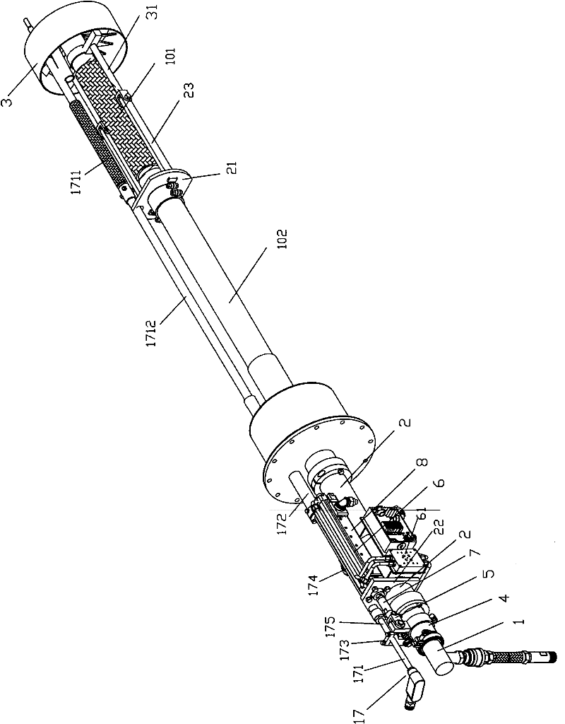
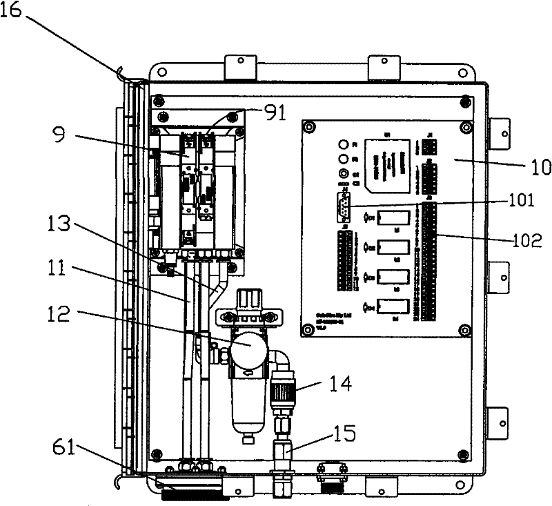
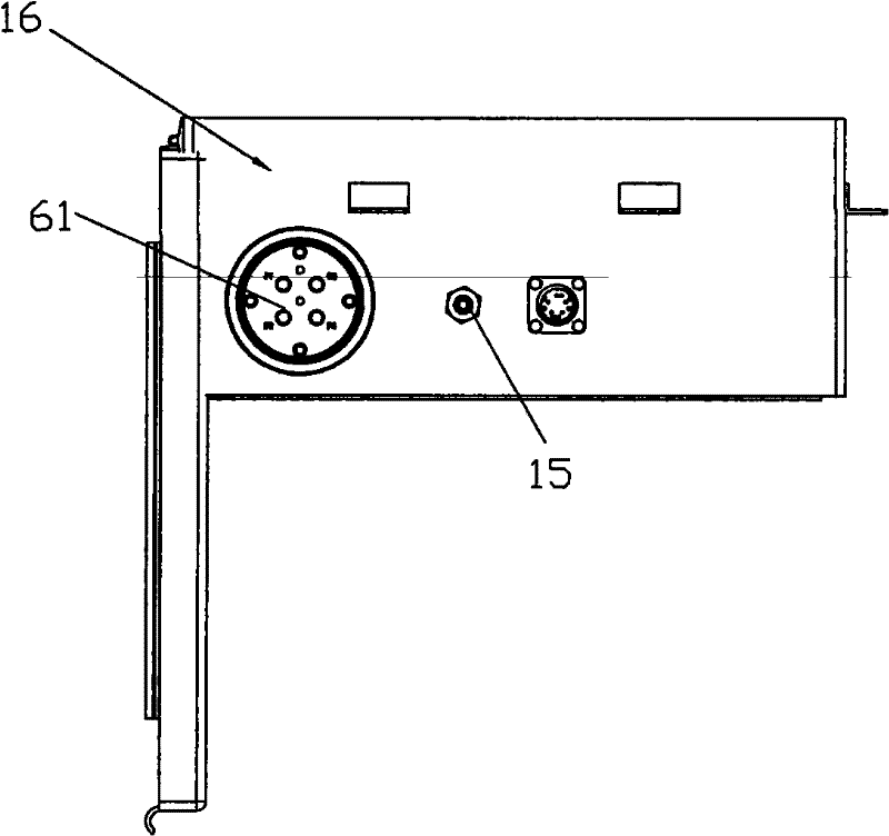
[0027] see figure 1 , figure 2 , image 3 , the boiler burner of the present invention comprises, oil gun gun body 1, and an outer casing 2 is arranged at the gun body rear portion; Stable combustion cover 3 is arranged on the end of oil gun gun body 1; On the rear part of the body 1, in the outer casing 2; the manipulator 5 is arranged on the traction pipe 4; the oil gun cylinder 6, the cylinder piston of the oil gun cylinder 6 is connected with the manipulator 5 through the pull rod 7; The gas source disc 61 of the source; the travel switch 8 is connected to the oil gun cylinder 6; a fixed plate 21, 22 is arranged on the described outer sleeve 2, and the fixed plate 21 is provided with two fixed rods 23 on one side of the front end of the gun body 1; The gun cylinder 6 is connected to the fixed plate 22; two connecting rods 31 are arranged on the stable combustion cover 3, and the connecting rods 31 and the fixed rod 23 on the outer casing 2 fixed plate 21 are hinged by b...


PUM


Abstract

The invention provides a combustor for a boiler, which comprises an oil gun body, a stable combustion sleeve, a traction tube, a mechanical arm, an oil gun air cylinder, an air source disc, a travel switch, a fixed plate, a connecting rod, a valve terminal, a valve terminal control board, an air filter reducing valve and a solenoid valve box, wherein the an outer sleeve is arranged at the rear part of the gun body; the stable combustion sleeve is arranged at the end part of the oil gun body; the traction tube is sleeved in the outer sleeve on the rear part of the gun body; the mechanical arm is arranged on the traction tube; a piston of the air cylinder is connected with the mechanical arm through a pull rod; the air source disc connected with an air source is arranged on the oil gun air cylinder; the travel switch is connected with the oil gun air cylinder; the fixed plate is arranged on the outer sleeve; a fixed rod is arranged at a side face of the fixed plate; the connecting rod is arranged on the stable combustion sleeve and is connected with the fixed rod; communication ports and wiring terminals are arranged on the valve terminal and the valve terminal control board; one end of the air filter reducing valve is connected with the valve terminal; the other end of the air filter reducing valve is connected with an air source pipe through a manual valve; and the valve terminal, the valve terminal control board, the air filter reducing valve and the manual valve are all arranged in the solenoid valve box. In the invention, larger deformation can be borne, and the blocking phenomenon of the oil gun due to deformation is avoided; and moreover, a control element avoids influences of high temperature, dust, oil stains and the like, therefore, the service life of equipment is greatly prolonged.

Description

technical field [0001] The invention relates to boiler equipment, in particular to a boiler burner. Background technique [0002] Among the power plant boilers that use oil burners as starting, combustion-supporting, and stable combustion, the four-cornered circular furnace is a common type of furnace. During the use of the oil gun, the deformation of the oil gun body due to the deformation of the hot and cold metal of the boiler is very easy. The pulling force generated when the burner swings often encounters a large deformation or even breakage of the metal hose of the outer casing of the oil gun. Both the solenoid valve and the travel switch are installed on the oil gun body, which is close to the furnace wall. The temperature is high, the dust is large, the oil pollution is large, and the environment is harsh, which brings great inconvenience to the debugging and maintenance of the equipment after the initial installation. Greatly increased the workload and difficulty o...

Claims


Application Information

Patent Timeline
Patent Type & Authority Patents(China)
IPC IPC(8): F23Q9/00
Inventor 马明黄志高叶正桂
Owner 西斐(上海)工业控制有限公司
Why Eureka
Try Eureka